Accurate flow measurement is essential to the safe, efficient, and economical operation of industrial plants. Whether the measured medium is natural gas, process liquid, steam, slurry, cooling water, or a contaminated industrial gas, the flow meter must provide stable readings under changing operating conditions. It must also tolerate pressure, temperature, vibration, deposits, wear, and limited installation space. The XG-V Series V-notch Flow Meters are designed to address these practical challenges with a differential-pressure measurement principle, a central V-shaped cone, and an annular throttling structure that produces reliable measurement with a relatively low permanent pressure loss.
Unlike many conventional throttling devices, the V-notch flow meter combines flow conditioning, self-cleaning action, broad application capability, and flexible instrumentation options in one system. Its specialized geometry helps improve velocity distribution inside the pipe, reduces the accumulation of dirt near the primary element, and minimizes the straight-pipe requirements normally associated with differential-pressure flow measurement. These characteristics make the meter suitable for new installations, plant expansions, and renovation projects where available pipeline space is restricted.
The XG-V Series operates according to the conservation laws of mass and energy. When a fluid flows through a pipeline containing a V-shaped throttling cone, the cone changes the flow area and creates a pressure difference between the upstream and downstream sides. This differential pressure is related to the flow velocity and volumetric or mass flow rate of the medium. A pressure-sensing system measures the differential pressure, and the flow transmitter converts the signal into a flow indication or an output signal for process control.
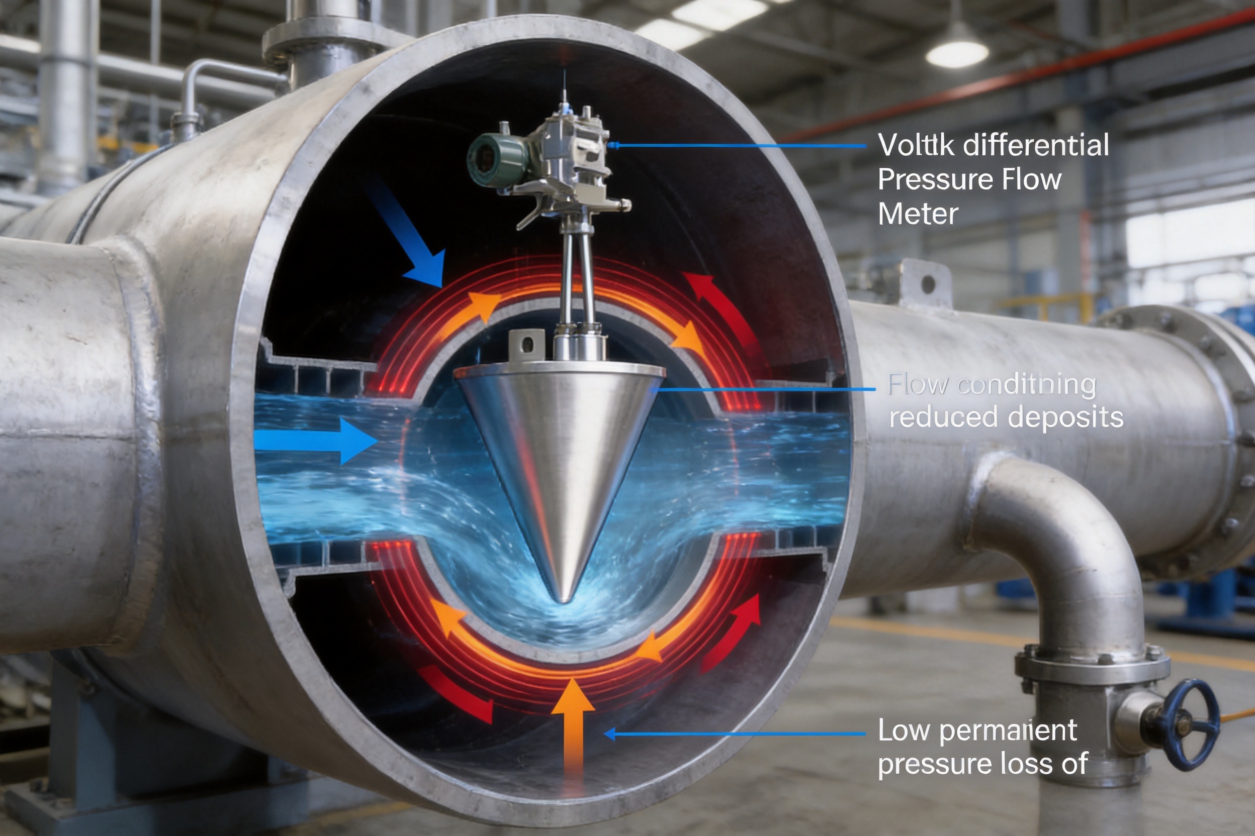
The V-shaped cone is suspended at the center of the pipeline rather than being formed as a sharp-edged opening in a flat plate. As the fluid approaches the cone, the flow is guided around its surface. The resulting annular flow path produces a controlled pressure differential while distributing the velocity profile more evenly around the pipe. This configuration gives the meter important advantages in applications where a standard orifice plate may be affected by deposits, erosion, insufficient straight pipe, or excessive energy loss.
For liquids, gases, saturated steam, and superheated steam, the appropriate measurement model and compensation method can be selected according to the process conditions. The system can be configured with no compensation, pressure compensation, temperature compensation, or full pressure and temperature compensation. This enables the meter to support both relatively simple flow monitoring and more advanced applications requiring compensated mass flow or standardized volume flow.
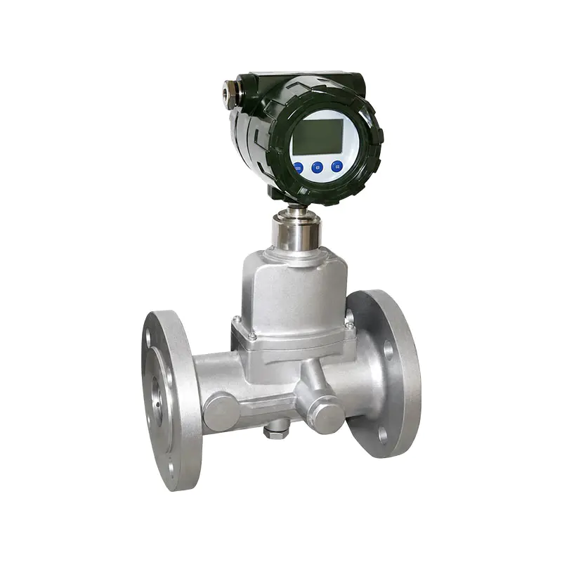
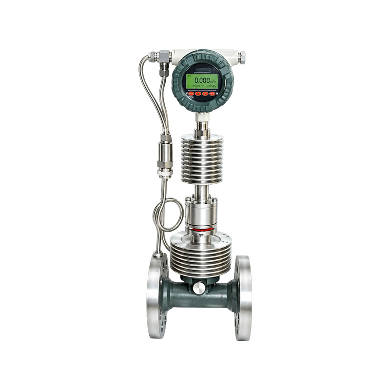
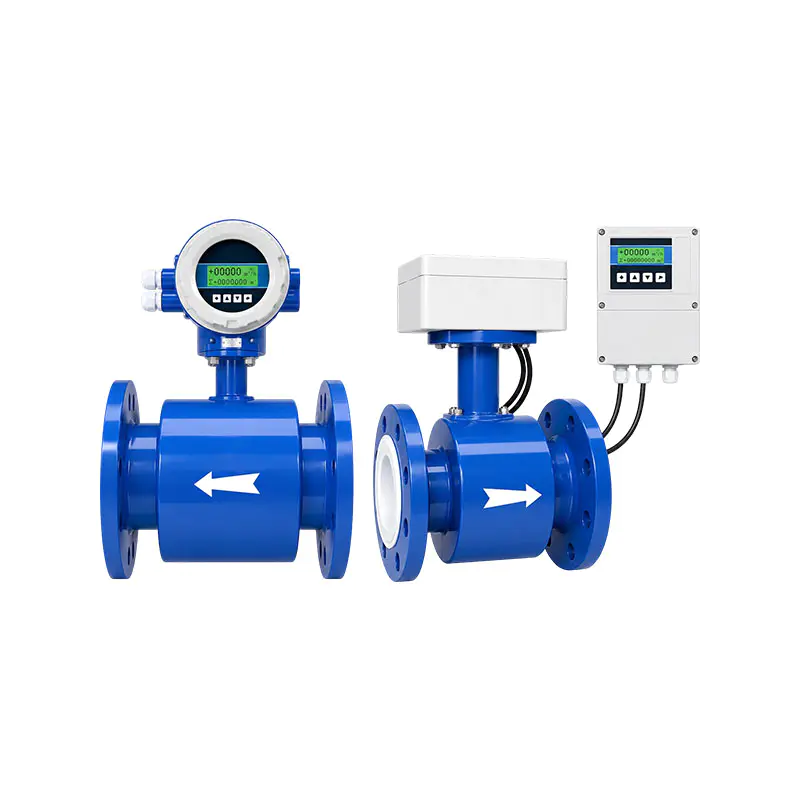
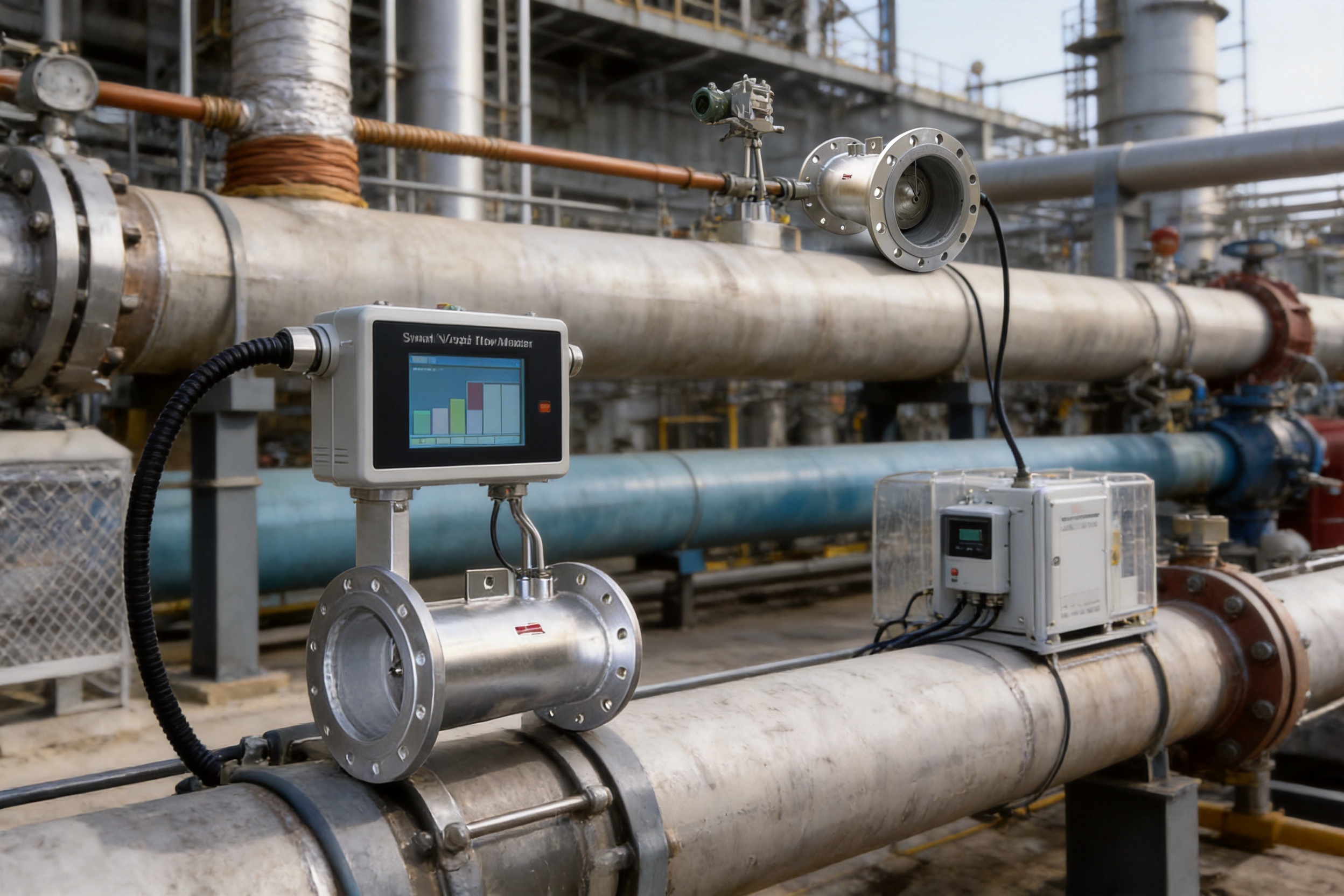
The measuring system may be supplied as an integrated smart unit or as a remote, split-type installation. An integrated configuration places the transmitter and primary flow element together, simplifying installation and reducing the amount of field wiring. A split configuration allows the display and electronics to be installed away from high-temperature, high-vibration, or difficult-to-access locations.
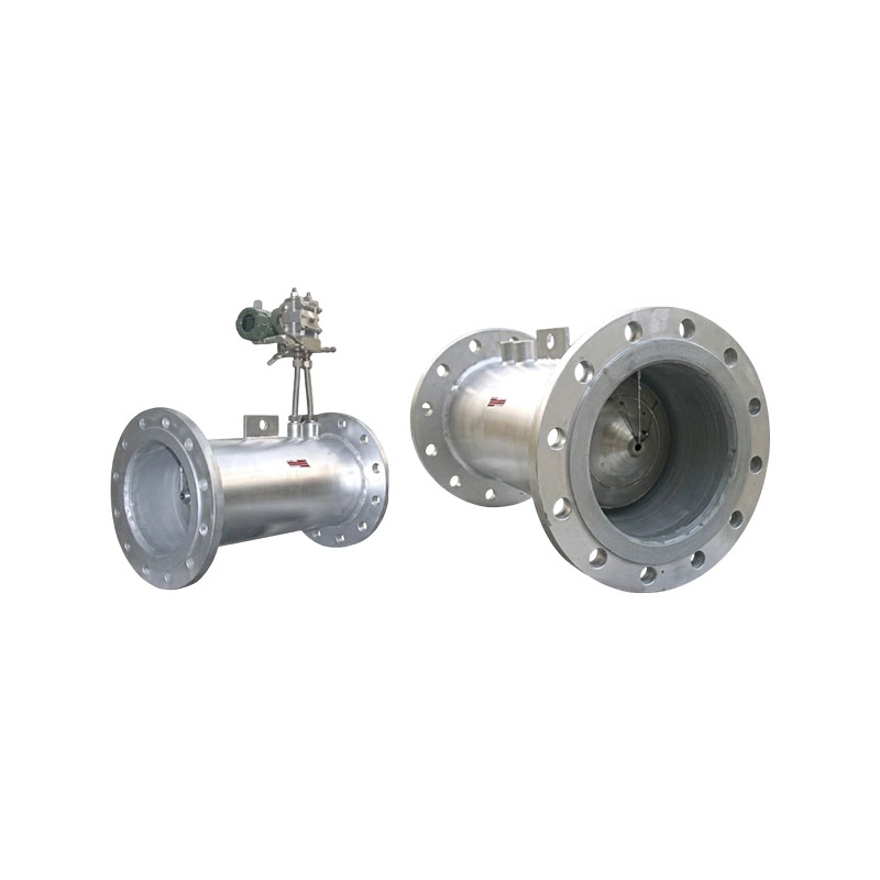
XG-V Series V-notch Flow Meters
One of the most significant advantages of a V-notch flow meter is its self-rectification effect. In a conventional pipeline, elbows, valves, reducers, expanders, pumps, and other fittings can distort the velocity profile. If a differential-pressure meter is installed too close to these disturbances, the resulting flow pattern may cause measurement error. Conventional systems may therefore require long upstream and downstream straight pipe sections, which can increase project cost and make installation impossible in compact facilities.
The central V-shaped cone changes the velocity distribution as the fluid passes through the meter. Flow velocity is reduced near the center and increased near the pipe wall. This action helps redistribute the flow profile and reduces the influence of upstream disturbances. Under suitable process conditions, the XG-V Series can generally be installed with approximately 0 to 3 nominal pipe diameters of upstream straight pipe and 0 to 1 nominal pipe diameter downstream.
The actual installation arrangement should always be reviewed against the pipeline layout, medium, Reynolds number, fittings, and required accuracy. However, the short straight-pipe requirement provides a major practical advantage. It is particularly useful in existing plants where moving equipment, cutting pipe, or adding long spool sections would interrupt production or require extensive civil and mechanical work.
Short installation lengths can reduce the quantity of pipe, supports, flanges, insulation, cable, and construction labor required for a project. They can also simplify engineering in skid-mounted systems, compact process units, boiler rooms, district-heating stations, and offshore or modular equipment packages. For replacement projects, the meter may fit into an available section of pipe without a major change to the original layout.
Industrial facilities are often expanded over several decades. Their pipelines may contain crowded equipment, irregular routing, short pipe runs, and limited access. A flow meter designed only for ideal laboratory conditions may be difficult to apply in such environments. The self-rectifying action of the V-notch design makes the XG-V Series more adaptable to actual plant conditions.
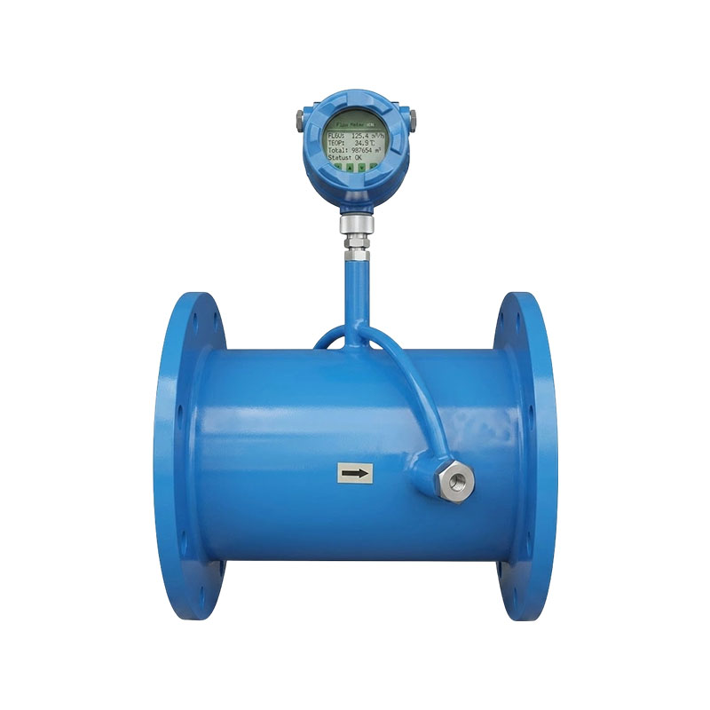
The meter is available in several body and connection forms, including pipe-type designs with slip-on or welding-neck flanges, flange-tapping configurations, direct-welded structures, wafer-type designs, insulation-jacket versions, corrosion-resistant versions, and special square-cone configurations. This range allows the engineering team to select a mechanical form that matches the existing process line and installation method.
Deposits and blockages are common causes of flow-meter failure. Dust, rust, scale, crystallized materials, suspended solids, condensate, viscous liquids, and process residue may accumulate around a primary element. In a conventional throttling plate, a small opening or sharp edge can become partially blocked. The resulting change in geometry may produce unstable readings, increased maintenance requirements, or a complete loss of measurement.
The XG-V Series uses an annular throttling structure that produces a self-blowing and self-cleaning effect. As the medium accelerates around the cone and along the annular passage, the local flow conditions make it difficult for contaminants to settle on the throttling element. This does not eliminate the need for appropriate process design or periodic inspection, but it significantly improves resistance to fouling compared with primary elements that provide a direct accumulation point.
This feature is valuable in applications involving dirty gas, gas containing dust, liquids with suspended particles, slurries, high-viscosity fluids, scaling fluids, and process streams that may crystallize. It is also useful where online cleaning is difficult or where shutting down the pipeline would be costly.
The self-cleaning effect contributes to long-term stability. If deposits change the effective flow passage, the differential-pressure relationship may drift over time. By reducing the tendency for material to build up, the V-notch geometry helps preserve the original measurement characteristics and reduces the frequency of manual cleaning.
Media quality and installation remain important. The meter should be selected with consideration for particle size, solids concentration, corrosivity, temperature, viscosity, pressure, and the possibility of coating or lining the wetted parts. Strongly corrosive media require compatible materials or a suitable corrosion-resistant construction. The V-notch principle improves adaptability, but it does not replace proper material selection.
Permanent pressure loss is an important operating cost in any flow-measurement system. When a throttling element consumes excessive pressure, a pump, compressor, or fan must provide additional energy to maintain the required process flow. Over an extended operating period, this energy penalty can be greater than the initial purchase price of the flow meter.
The special cone structure of the XG-V Series is designed to achieve a lower pressure loss than a traditional orifice plate. Under comparable operating conditions, the pressure loss may be approximately one-third to one-fifth that of an orifice-plate throttling device. The exact value depends on the selected differential pressure, flow rate, pipe size, medium properties, and process configuration.
Lower pressure loss is especially beneficial in large-diameter pipelines, continuous-production facilities, compressed-gas systems, steam networks, water distribution systems, and applications where pumping or compression energy represents a significant part of operating expenditure. Reduced energy consumption may also support plant sustainability objectives and lower the indirect environmental impact of the process.
A lower pressure loss can provide operational flexibility as well. The process may continue to achieve the required flow rate with less available pump head or compressor capacity. Alternatively, the plant may use the saved pressure margin to accommodate future production increases, additional equipment, or changes in process resistance.
The meter should not be selected only on the basis of pressure-loss claims. Engineers should calculate the complete system pressure balance and confirm the actual operating point. Nevertheless, the combination of a stable differential-pressure signal and relatively low permanent pressure loss gives the V-notch meter a strong advantage over simple, high-loss throttling devices.
Industrial flow rates rarely remain constant. Production may change between day and night shifts, seasonal demand may affect utility networks, and equipment may operate at startup, normal load, turndown, and emergency conditions. A flow meter with a narrow usable range may provide acceptable accuracy at one operating point but perform poorly at low flow or overload conditions.
The XG-V Series offers a nominal range ratio of 10:1, with special configurations capable of reaching approximately 30:1. Rangeability depends on the selected primary element, transmitter, differential-pressure range, medium, and accuracy requirement. A broad range allows one meter to cover a wider operating envelope without requiring frequent replacement or mechanical adjustment.
The absence of moving parts improves repeatability and reduces mechanical wear. There is no rotating impeller, sliding component, or mechanical bearing that must remain free to operate. This is particularly helpful in dirty streams, high-temperature service, and pipelines where maintenance access is limited.
Good wear resistance and low long-term accuracy attenuation support stable measurement over extended operation. The cone and body materials can be selected to suit the process environment. For severe service, the engineering specification should address erosion velocity, corrosion allowance, lining requirements, temperature cycling, and the compatibility of pressure-sensing connections.
Stable measurement is valuable not only for display purposes but also for control loops, custody-related monitoring, production accounting, boiler management, energy management, and process optimization. A repeatable signal enables operators and control systems to distinguish actual process changes from instrument drift.
The XG-V Series is designed for multiple classes of industrial media. The product coding system allows the measured medium to be identified as liquid, gas, or steam. The proper configuration must be selected according to density, viscosity, compressibility, temperature, pressure, corrosivity, and flow range.
Liquid applications may include circulating water, feedwater, condensate, crude oil, refined oil, chemical process liquids, cooling water, and liquids containing suspended solids. The meter is suitable for applications in which a stable differential-pressure signal is required and where the liquid may be contaminated, viscous, or prone to scaling.
For liquids, the installation should prevent unwanted gas pockets in the sensing lines and should provide an appropriate orientation for the pressure connections. The process engineer should also verify that the differential pressure remains compatible with the available liquid head and that flashing or cavitation will not occur near the throttling element.
Gas measurement applications include natural gas, coal gas, compressed air, process gas, blast furnace gas, coke oven gas, flue gas, and other industrial gas streams. Gas density changes with pressure and temperature, so pressure and temperature compensation may be needed when the process requires accurate mass flow or standardized volume flow.
Dirty gas service benefits from the self-cleaning annular structure. Even so, the gas composition should be reviewed for corrosive components, moisture, dust loading, condensable materials, and possible hydrate or crystallization problems. Appropriate impulse-line design, drainage, heat tracing, or separation equipment may be required.
The meter can be applied to saturated steam and superheated steam. Steam flow measurement is common in thermal power plants, process factories, district-heating systems, food plants, chemical plants, and manufacturing facilities. Steam systems often require compensation because density changes significantly with pressure and temperature.
For high-temperature steam, the transmitter may be installed remotely or supplied with suitable impulse-line and insulation arrangements. The product family is designed for working temperatures up to approximately 850 degrees Celsius and pressures up to approximately 42 MPa when the appropriate construction and materials are used. The final rating must be confirmed for the selected body, flange, sensing connection, gasket, transmitter, and process accessories.
A correct configuration begins with the process data. The nominal diameter, body structure, pressure rating, measured medium, compensation mode, output signal, power supply, and connection method should all be specified before production. The XG-V coding system supports systematic selection and helps align the finished meter with the plant's mechanical and electrical requirements.
| Selection Item | Available Option | Typical Purpose |
|---|---|---|
| Structure type | Integrated smart or remote split type | Local installation or separated electronics for harsh environments |
| Measured medium | Liquid, gas, or steam | Selection of the appropriate calculation and compensation model |
| Body type | Slip-on flange, welding-neck flange, flange tapping, direct welded, wafer, jacketed, corrosion-resistant, or special cone forms | Adaptation to piping, process connection, insulation, and material requirements |
| Static pressure range | 0 to 0.6 MPa through 0 to 40 MPa | Matching the pressure class of the process line |
| Compensation | None, pressure only, temperature only, or full pressure and temperature | Improving flow calculation under variable process conditions |
| Signal output | None, 4-20 mA, pulse, or HART | Connection to control systems, totalizers, or intelligent asset networks |
| Power supply | Internal battery, battery plus 24 VDC, or external 24 VDC | Adapting the instrument to available site power |
The integrated smart configuration combines the primary flow element, pressure measurement system, processing electronics, display, and communication functions in one instrument assembly. It is suitable when local indication and a compact installation are preferred. The large LCD can display flow information and operating parameters, allowing technicians to check the process without always relying on a separate control-room system.
Advanced internal memory helps protect measurement data and configuration information. Depending on the selected electronics, the instrument can provide 4-20 mA output, pulse output, and HART communication. Battery operation may be selected for locations where external power is unavailable, while a dual battery and 24 VDC supply can offer additional flexibility.
The remote split configuration separates the sensing and display electronics. This arrangement is useful when the primary flow element is installed in a hot pipeline, a vibrating machine area, a confined space, or a location exposed to weather or corrosive atmosphere. The transmitter can be mounted at a more accessible position for commissioning, inspection, and maintenance.
Remote installation also allows the display to be positioned at an operator platform or instrument panel. The engineering team should determine the maximum permissible signal-cable length, grounding method, environmental protection, cable routing, and separation from high-voltage or high-frequency equipment.
The intelligent integrated V-notch flow meter uses advanced circuit design to process differential-pressure information and calculate flow-related parameters. Its functions are designed to balance measurement capability, low power consumption, display clarity, and communication convenience.
The 4-20 mA output remains widely used because it is compatible with distributed control systems, programmable logic controllers, panel meters, and industrial data-acquisition systems. Pulse output can be used for totalization or connection to a flow counter. HART communication provides access to configuration, diagnostic information, measured values, and other digital functions while retaining compatibility with a conventional analog signal loop.
Battery-powered operation can reduce installation complexity in remote locations. The battery selection must consider update frequency, display use, ambient temperature, output mode, communication activity, and required service life. Where a reliable 24 VDC supply is available, external power may be preferred for continuous communication and frequent data access.
The internal memory supports data security and helps retain important instrument information. During commissioning, operators should document the configured pipe diameter, medium, density assumptions, compensation settings, output scaling, alarm limits, and calibration information. Good configuration management is essential to achieving the full performance of any intelligent flow meter.
The performance of a flow meter depends not only on its design but also on the quality of materials, machining, welding, assembly, calibration, electronics, and final inspection. Xinguo Group Co., Ltd. operates as a national high-technology enterprise with business units covering instrumentation, alloy materials, cables, and precious metals. This broad manufacturing base supports a coordinated approach to industrial product development.
The group was founded in 1997 and is located in Tianchang City, Anhui Province, China. Its facilities cover more than 150 mu of land and include approximately 60,000 square meters of construction area. The organization employs nearly 300 people, including more than 50 professional technicians, senior technical experts, senior engineers, engineers, and assistant engineers.
This technical workforce provides a foundation for product design, material selection, process development, electrical engineering, testing, and customer support. A flow meter intended for petroleum, chemical, power, metallurgy, and utility applications must be developed with an understanding of both instrumentation theory and real industrial operating conditions.
The group companies include an alloy manufacturer, a cable manufacturer, a precious-metal business, and instrumentation manufacturers. This structure can support closer coordination of material specifications and product requirements. Alloy expertise is particularly relevant where high-temperature components, thermocouple materials, corrosion resistance, and specialized industrial alloys are involved.
For the V-notch flow meter, material selection may involve the body, cone, pressure-sensing parts, flanges, impulse connections, gaskets, lining, insulation jacket, and electronic enclosure. The selected materials must withstand the pressure, temperature, chemical composition, erosion, and mechanical stresses of the application. Material certificates and traceability should be requested when required by the project specification.
Manufacturing quality is supported by modern equipment, contemporary production techniques, and inspection procedures applied throughout the manufacturing process. Critical steps may include material verification, dimensional inspection, machining, welding inspection, pressure testing, surface treatment, assembly, electronic testing, calibration, and final performance verification.
Dimensional control is important because the cone geometry and annular flow passage directly influence the pressure differential. Flange alignment, tapping position, internal diameter, surface condition, and concentricity must be controlled within the applicable design tolerances. Poor dimensional consistency can create unnecessary uncertainty even when the theoretical measurement principle is sound.
Pressure-containing parts require careful attention to welding quality, non-destructive examination where specified, pressure testing, and leak prevention. The final assembly must also protect the sensing system from vibration, moisture, temperature extremes, and mechanical damage during transportation and field installation.
Xinguo Group has obtained ISO 9001 Quality Management System certification, ISO 14001 Environmental Management System certification, and GB/T 28001 Occupational Health and Safety Management System certification. These systems demonstrate a structured approach to quality control, environmental responsibility, and workplace safety.
A quality management system helps establish controlled procedures for purchasing, production, inspection, nonconformance handling, corrective action, document control, and customer feedback. For an industrial flow meter, such controls are valuable because the product may be installed in safety-critical or economically important process lines.
The company's stated quality principles include customer focus, consistent quality, continuous improvement, and pursuit of excellence. These principles are especially relevant to customized flow-meter projects, where the final configuration must reflect process data, piping details, communication requirements, and local installation conditions.
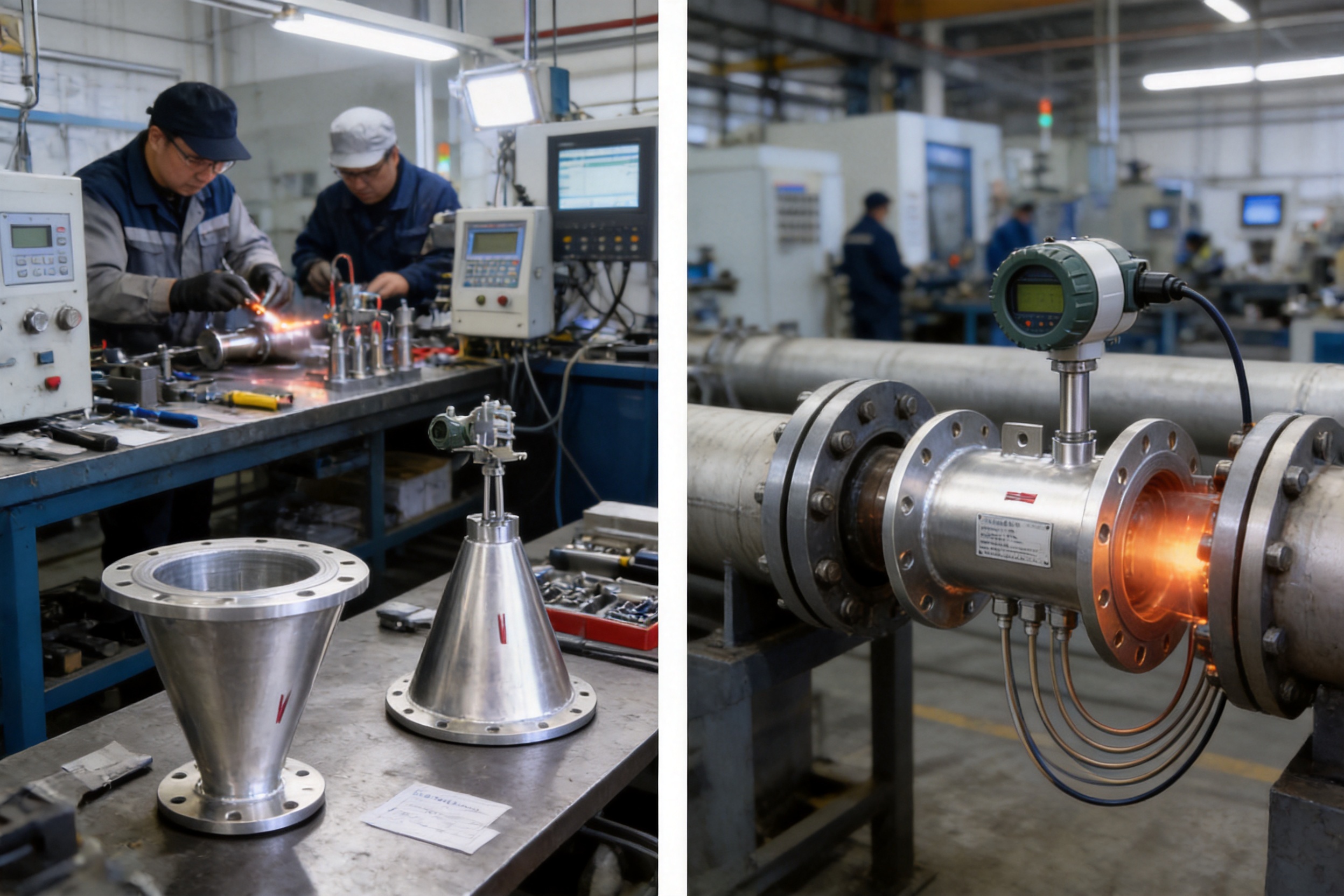
In petroleum and natural-gas facilities, flow meters may be used for process monitoring, utility measurement, production control, and trade-related measurement subject to the applicable standards and verification requirements. Crude oil, refined products, natural gas, and oil-and-gas mixtures may contain impurities that challenge conventional instruments.
The XG-V Series is suitable for selected applications involving contaminated or difficult media because of its self-cleaning structure, absence of moving parts, and resistance to wear. Gas applications may require pressure and temperature compensation to account for changing operating conditions. Material compatibility, hazardous-area requirements, grounding, and certification must be addressed during project design.
Chemical plants commonly measure process gases, steam, corrosive fluids, slurries, and liquids that are prone to crystallization. Many of these media are difficult to measure with instruments containing small passages or delicate moving components. A V-notch primary element can provide a robust alternative when the material and pressure class are correctly selected.
For corrosive service, the wetted materials, lining, sealing components, and pressure-sensing connections must be reviewed against the complete chemical composition and operating temperature. The product is not automatically suitable for every strongly corrosive medium. A corrosion-resistant or lined version may be required, and the supplier should receive complete process information before confirming the selection.
Power plants and heating projects use flow meters for boiler steam, feedwater, condensate, cooling water, gas, flue gas, and auxiliary systems. Steam and water lines often operate continuously, making maintenance reduction and stable long-term measurement particularly important.
The low pressure loss of the V-notch structure can help reduce energy waste in large utility lines. The short straight-pipe requirement can simplify installation in crowded boiler rooms and plant utility areas. Remote electronics may be selected for high-temperature lines, while pressure and temperature compensation can support more accurate steam-flow calculations.
Metallurgical plants measure blast furnace gas, coke oven gas, circulating water, compressed air, slurry, and other industrial media. These environments may involve dust, vibration, high temperature, corrosive compounds, and irregular process conditions. A flow meter with no moving parts and a self-cleaning throttling structure is well suited to many of these duties.
Application engineering should consider the gas composition, dust concentration, moisture content, pipe temperature, vibration level, and required signal transmission distance. Special materials, insulation, remote mounting, or protective enclosures may be specified to support reliable operation.
Orifice plates remain widely used because they are simple, standardized, and familiar to many engineers. However, they can require substantial straight pipe, create relatively high permanent pressure loss, and experience accuracy changes when the sharp edge becomes worn or contaminated. Their small opening may also be vulnerable to blockage when the medium contains solids, deposits, or viscous components.
The V-notch meter addresses these weaknesses through its central cone and annular flow passage. Its self-rectification reduces the straight-pipe requirement. Its self-cleaning action makes it more tolerant of dirty or scaling media. Its non-moving structure improves repeatability and reduces mechanical maintenance. Its relatively low pressure loss can reduce energy consumption, particularly in high-flow systems.
The comparison should be made using complete project data rather than general statements. An orifice plate may be appropriate for a clean, stable, standardized service with ample straight pipe and acceptable pressure loss. A V-notch meter becomes especially attractive when the pipeline is compact, the medium is contaminated, the operating range is broad, or the permanent pressure loss must be minimized.
| Performance Consideration | V-Notch Flow Meter | Conventional Orifice Plate |
|---|---|---|
| Straight-pipe requirement | Generally short because of self-rectification | Often longer and more dependent on upstream fittings |
| Resistance to deposits | Annular structure provides self-cleaning and self-blowing action | Small opening and edge may be affected by fouling |
| Moving parts | None | None, but the sharp edge may wear |
| Permanent pressure loss | Relatively low; commonly stated as about one-third to one-fifth of an orifice plate under comparable conditions | Relatively high |
| Rangeability | Approximately 10:1, with special configurations up to about 30:1 | Often more limited in practical operation |
| Large-diameter service | Plug-in versions can reduce sensor and installation costs | Large plates and associated pressure loss may increase project burden |
| Application flexibility | Suitable for selected liquids, gases, and steam, including difficult media | Best suited to properly conditioned and compatible media |
Large-diameter pipelines can make conventional flow-meter installation expensive. A full-bore primary element may require large flanges, heavy supports, extensive welding, and significant shutdown time. The cost of the sensor and associated construction can become disproportionate to the value of the measurement point.
The plug-in XG-V cone flow-meter system is intended to address this challenge. It retains the essential advantages of V-cone measurement while reducing the cost and installation burden associated with very large pipe diameters. The system can also help address the problem of small differential pressure in large pipes, where a conventional arrangement may produce a signal that is inconvenient to measure or process.
Plug-in designs require careful engineering of the insertion point, sealing arrangement, support structure, insertion depth, pressure taps, and maintenance access. The pipe interior must be evaluated to ensure that the cone is correctly positioned and that the installation does not interfere with other internal components. When properly engineered, the approach can provide a practical balance of economy, installation speed, stability, and measurement performance.
Accurate product selection depends on complete process information. The purchaser should provide the inner diameter and outer diameter of the pipe, the pipe material, and the nominal pipe size. Wall thickness and internal lining should also be identified because they influence the actual flow passage and connection design.
Process flange specifications should include flange standard, pressure class, facing type, material, bolt pattern, and sealing requirements. If the pipe is directly welded, the supplier should receive the welding and end-preparation details. For insulated or jacketed service, the insulation thickness and heating or cooling requirements should be stated.
The measured medium must be clearly identified. For liquids, provide the fluid type, density, viscosity, temperature range, pressure range, minimum flow, normal flow, maximum flow, and solids content where applicable. For gases, provide composition, molecular weight or density, pressure, temperature, compressibility information if available, moisture content, and expected contamination. For steam, specify whether it is saturated or superheated and provide pressure, temperature, dryness, and flow range.
The project should also define the required output, display, communication protocol, power source, hazardous-area classification, environmental protection level, calibration requirements, and applicable standards. Clear information at the quotation stage reduces the risk of selecting an unsuitable pressure range, material, compensation mode, or connection structure.
Before installation, inspect the meter for transportation damage and verify the nameplate, flow direction, nominal diameter, pressure rating, flange details, and electrical configuration. The pipeline should be clean enough to prevent welding slag, rust, construction debris, or sealing material from entering the sensing connections.
The flow direction must match the arrow or installation marking. Flanges should be aligned without forcing the meter into position. Excessive mechanical stress can deform the body, damage the cone, or create leakage. Gaskets should be selected for the medium, pressure, and temperature, and they should not protrude into the flow passage.
Pressure-sensing lines should be routed to avoid unnecessary high points, low points, sharp bends, vibration, and temperature extremes. Liquid service may require arrangements that prevent gas accumulation. Gas service may require condensate drainage or heating. Steam service generally requires appropriate impulse-line geometry, condensate management, and protection of the transmitter from excessive temperature.
After installation, verify electrical polarity, grounding, signal scaling, communication, display settings, and alarm parameters. The zero point should be checked under the appropriate no-flow condition. For compensated applications, confirm the pressure and temperature inputs, sensor ranges, units, and calculation settings.
Although the V-notch structure reduces fouling and maintenance, periodic inspection remains good practice. Maintenance intervals should be based on the medium, operating severity, historical stability, and criticality of the measurement. Inspection may include checking flange leakage, impulse-line condition, wiring, display operation, output signal, grounding, and diagnostic information.
A flow meter should be evaluated over its entire lifecycle rather than only by its purchase price. Installation labor, energy consumption, calibration frequency, spare parts, production interruptions, cleaning requirements, and replacement costs can have a greater financial impact than the initial instrument cost.
The XG-V Series provides lifecycle advantages through short straight-pipe requirements, low pressure loss, resistance to deposits, broad rangeability, and a design without moving parts. These features can reduce installation complexity, improve operating stability, and lower the likelihood of unplanned maintenance.
Safety is also influenced by measurement reliability. Stable flow data supports process control, prevents overloading, helps identify abnormal operating conditions, and contributes to safe management of steam, gas, chemical, and high-pressure systems. The instrument should be integrated into the plant's safety and maintenance procedures, with appropriate inspection and calibration practices.
Environmental considerations include energy consumption, material selection, production controls, and responsible manufacturing. The supplier's ISO 14001 environmental management certification indicates that environmental management is incorporated into its organizational systems. Customers should nevertheless evaluate the complete application, including pressure loss, power consumption, maintenance waste, and end-of-life handling.
The XG-V Series combines several advantages that are rarely available together in a conventional differential-pressure flow-meter package. Its V-shaped central cone creates a stable pressure differential while helping to condition the flow. Its annular passage supports self-cleaning action in difficult media. Its lack of moving parts improves repeatability and reduces mechanical wear. Its low pressure loss helps limit energy consumption. Its range of approximately 10:1, with special configurations reaching about 30:1, supports changing process loads.
The meter is also adaptable to real plant constraints. Short upstream and downstream straight-pipe requirements make it useful for compact installations and renovation projects. Integrated and remote configurations address different environmental and maintenance needs. Battery, 24 VDC, 4-20 mA, pulse, and HART options support a variety of automation architectures. Different body styles, pressure ranges, compensation modes, and connection arrangements allow the product to be configured for a wide range of process systems.
These product characteristics are reinforced by the manufacturing and engineering capabilities of Xinguo Group. Its experience in industrial instrumentation, alloy materials, cables, and related products supports a coordinated approach to design and production. Its technical workforce, production facilities, inspection procedures, and certified management systems provide a foundation for consistent manufacturing and customer support.
For engineers comparing flow-meter technologies, the most important question is not simply whether a meter can measure flow under ideal conditions. The more practical question is whether it can continue to provide useful, stable data when the pipeline is crowded, the medium is dirty, the process load varies, energy efficiency matters, and maintenance opportunities are limited. The XG-V Series is specifically designed around these conditions.
No. The V-shaped cone provides a self-rectification effect that reduces the influence of upstream disturbances. The general requirement is approximately 0 to 3 nominal pipe diameters upstream and 0 to 1 nominal pipe diameter downstream, subject to the actual piping arrangement and application conditions. The installation should still be reviewed by the supplier or process engineer.
Yes, the annular throttling structure is designed to provide a self-blowing and self-cleaning effect. It can be used for selected liquids, gases, and slurries containing particles, deposits, scale, or high-viscosity components. Material compatibility, particle concentration, erosion, and process temperature must be considered before final selection.
The main advantages are a shorter straight-pipe requirement, lower permanent pressure loss, wider practical rangeability, better resistance to deposits, good wear resistance, and stable long-term repeatability. The exact comparison depends on pipe size, medium, flow range, differential-pressure setting, and required accuracy.
The XG-V Series can be configured for liquids, gases, saturated steam, and superheated steam. Typical applications include oil, natural gas, coal gas, process gas, circulating water, feedwater, condensate, compressed air, boiler steam, and chemical process fluids. Strongly corrosive media require compatible materials or suitable lining.
The product family is suitable for working temperatures up to approximately 850 degrees Celsius when the proper structure, materials, pressure connections, insulation, and transmitter arrangement are selected. The final allowable temperature must be confirmed for the complete instrument assembly rather than the primary element alone.
Available static-pressure options range from approximately 0 to 0.6 MPa through 0 to 40 MPa in the listed configuration system. Higher or special ratings may be possible with suitable materials and engineering. The selected flange, body, gasket, sensing line, and transmitter must all be compatible with the process pressure.
Yes. The configuration may include no compensation, pressure compensation only, temperature compensation only, or full pressure and temperature compensation. Compensation should be selected according to the medium and the required flow output, particularly for gases and steam.
Yes. The meter can be supplied in an integrated smart structure or a remote split structure. Remote mounting is useful for high-temperature pipelines, areas with strong vibration, difficult access locations, or installations where the display and electronics need to be positioned at an operator station.
Depending on the selected configuration, the system can provide 4-20 mA output, pulse output, and HART communication. The available power options include an internal battery, battery plus selectable 24 VDC, or external 24 VDC.
Provide the pipe inner and outer diameters, pipe material, nominal size, flange specifications, medium type, minimum and maximum flow rates, operating pressure, operating temperature, density, viscosity, gas composition, steam condition, required accuracy, compensation requirements, output signals, power supply, and environmental or hazardous-area requirements.
The XG-V Series V-notch Flow Meters offer a practical and technically capable solution for industrial flow measurement. Their central V-shaped cone produces a reliable differential-pressure signal while providing self-rectification and self-cleaning effects. The result is a flow meter that can operate with short straight-pipe sections, tolerate a broad selection of process media, reduce permanent pressure loss, and maintain stable measurement without moving parts.
From petroleum and natural gas to chemical processing, electric power, district heating, and metallurgy, the meter is designed for applications where process conditions are demanding and maintenance access is limited. Integrated and split configurations, multiple body styles, compensation options, communication functions, and flexible power supplies make the system adaptable to both new projects and plant renovation.
Supported by Xinguo Group's instrumentation experience, technical workforce, material capabilities, modern production facilities, inspection procedures, and certified management systems, the XG-V Series represents more than a primary flow element. It is a complete industrial measurement solution developed for reliability, energy efficiency, installation flexibility, and long-term process value.
1. Xinguo Group Co., Ltd., XG-V Series V-Notch Flow Meter Product Information.
2. Xinguo Group Co., Ltd., Product Configuration and Ordering Information for Differential-Pressure Flow Instruments.
3. International Electrotechnical Commission, Industrial-Process Measurement and Control Practices.
4. International Organization for Standardization, Quality Management Systems—Requirements.
5. International Organization for Standardization, Environmental Management Systems—Requirements with Guidance for Use.
6. General industrial engineering principles for differential-pressure flow measurement, pressure-loss evaluation, and process instrumentation installation.



 INQUIRY
 English
 عربى
 русский
 中文简体