Flow measurement is a fundamental requirement in process control, utility management, environmental protection, and production safety. A flow meter must do more than display a number. It must remain stable when the process temperature changes, withstand the pressure and chemical conditions of the medium, tolerate vibration, and provide information that operators can trust. In many industrial installations, the flow meter is also expected to operate with limited maintenance, fit into restricted spaces, and communicate with a control system.
The XG-JF Series Metal Float Flow Meter is designed for these demanding requirements. It is a variable area flow measurement instrument with a metal measuring tube and float-based operating principle. The series is suitable for liquids, gases, and vapors, particularly where the measured medium has a low flow velocity or a relatively small flow rate. Its compact construction, broad measuring capability, optional intelligent indication, and range of process connections allow it to serve as both a straightforward local indicator and a digitally integrated industrial instrument.
Unlike a simple glass tube rotameter, a metal float flow meter is designed for applications where pressure, temperature, vibration, corrosion, or mechanical impact make transparent glass equipment unsuitable. At the same time, it retains the direct and intuitive operating principle associated with variable area meters. The operator can observe the local reading, while selected configurations can provide 4–20 mA output, alarm functions, pulse output, backlighting, HART communication, or Modbus communication.
Manufactured by Xinguo Group Co., Ltd., a Chinese industrial instrumentation and materials enterprise established in 1997, the series benefits from the group’s experience in temperature instruments, pressure instruments, flow meters, level instruments, alloy materials, cables, and related industrial products. The company combines research and development, material production, machining, instrument assembly, calibration, inspection, and quality management within an integrated manufacturing organization.
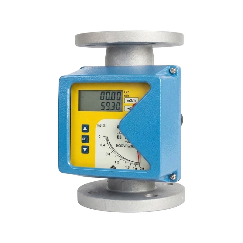
XG-JF Series Metal Float Flow Meter
A variable area flow meter measures flow by allowing a float to move inside a tapered measuring tube. As the fluid enters the tube from below, it lifts the float. The float rises until the upward force created by the flowing medium balances the weight of the float and the forces acting on it. The position of the float corresponds to the flow rate and is displayed on a calibrated scale or converted into an electronic output.
In a metal float flow meter, the measuring tube is not transparent. Instead, the float position is transferred magnetically or mechanically to an external indicator. The XG-JF Series uses a sensitive single-axis indication structure and non-contact magnetic coupling capability. This arrangement allows the flow position inside the process tube to control the external display without requiring a direct mechanical penetration through the pressure boundary.
The operating principle is simple, but the engineering around it is important. The tube must have the correct internal geometry, the float must be manufactured for the intended density and flow range, and the indicator must translate the float position accurately. The process materials, connection design, damping arrangement, and calibration must also match the application.
One important advantage of the variable area principle is that it can measure relatively low flow rates without requiring a complex high-speed sensing system. It does not depend on a large pressure drop in the same way as some differential-pressure devices. It can therefore be useful for purge gas, cooling water, sampling systems, chemical dosing, auxiliary process streams, and other services where a moderate or low flow must be monitored continuously.
The basic local indicator can display the flow rate without an external power supply. This is valuable in utility areas, remote skids, equipment rooms, and hazardous or difficult-to-wire locations where the operator needs a direct reading but does not require a control-system signal.
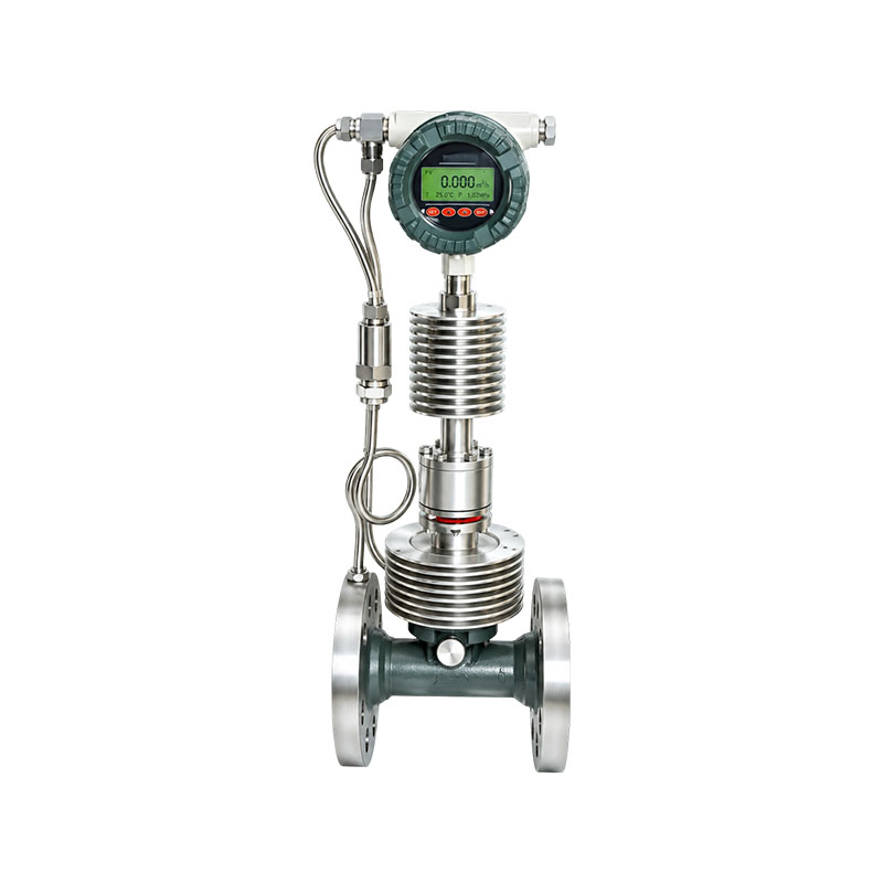
For installations that require remote monitoring, the series can be configured with electronic indication and output functions. Depending on the selected indicator and power option, the instrument may provide 4–20 mA transmission, relay alarm functions, pulse output, LCD display, backlighting, HART protocol, or Modbus protocol. This gives users a choice between a fully local instrument and a more advanced flow transmitter.
The principal difference between a metal float flow meter and a glass tube flow meter is the process boundary. Glass provides excellent visibility, but it has limitations in pressure resistance, temperature resistance, mechanical impact resistance, and suitability for hazardous service. A metal tube provides a stronger enclosure for the fluid and float, making it more appropriate for demanding industrial conditions.
The XG-JF Series can be supplied with different wetted materials, including stainless steel grades, titanium alloy, and PTFE-lined or PTFE-related configurations according to the selected model. Material selection should be based on the chemical composition, concentration, temperature, pressure, and cleanliness of the medium. The availability of these choices allows the instrument to be adapted to ordinary water service, corrosive chemical applications, high-purity duties, and specialized process conditions.
The series is available in several measuring tube structures. The standard configuration uses bottom inlet and top outlet flow, while other arrangements can provide bottom inlet with horizontal outlet, horizontal inlet and outlet, or side-entry and side-exit configurations. This is useful when pipe routing, installation space, skid design, or existing equipment connections make a conventional vertical arrangement inconvenient.
Although the measuring principle remains consistent, the structural variations can simplify installation and maintenance. A suitable configuration can reduce the need for additional elbows, piping modifications, or difficult access around the instrument. The correct selection must still respect the manufacturer’s installation instructions and the requirements for stable flow conditions.
| Design or option | Available capability | Practical benefit |
|---|---|---|
| Measuring tube structure | Vertical and selected horizontal or side-entry arrangements | Improved adaptation to different piping layouts |
| Wetted materials | Stainless steel, titanium alloy, PTFE-related options, and other specified materials | Selection for corrosion resistance and process compatibility |
| Indicator | Mechanical pointer, LCD-based indicator, or multifunction indicator | Choice between simple local reading and advanced display functions |
| Power supply | No-power local indication, battery, 24 VDC, or 85–265 VAC options | Compatibility with local and plant-wide power systems |
| Signal output | 4–20 mA, relay alarm, pulse output, HART, or Modbus options | Integration with control, monitoring, and data systems |
| Environmental options | Damping, jacket, high-temperature, and high-pressure configurations | Adaptation to unstable, heated, pressurized, or specialized media |
The XG-JF Series is designed with a wide flow ratio. The supplied product information identifies a flow ratio of up to 10:1, allowing one instrument to cover a relatively broad operating range. The published selection information also indicates water flow measurement from approximately 1 to 200,000 liters per hour and air flow measurement from approximately 0.03 to 4,000 cubic meters per hour under specified reference conditions. Actual capacity depends on tube size, float design, fluid density, viscosity, pressure, temperature, and the selected material and indicator configuration.
The series is available for nominal pipe sizes from DN15 to DN200, subject to the specific model and structure. This range supports small auxiliary lines as well as larger utility and process pipelines. The instrument can therefore be used in laboratory support systems, equipment cooling circuits, chemical feed lines, compressed air services, water treatment plants, and industrial process networks.
The stated accuracy options are 1.0% of full scale and 1.5% of full scale. Users should distinguish full-scale accuracy from percentage-of-reading accuracy. When the operating point is close to the lower end of the scale, the absolute error represented by a full-scale specification can become more significant. For this reason, the selected range should place the normal operating flow within the most useful part of the scale rather than at the extreme bottom.
The series also supports multi-parameter calibration. This is especially useful when the application involves gases or fluids whose density changes with temperature and pressure. A calibrated instrument must be matched to the actual process conditions, not only to the nominal pipe size. Providing the correct medium data during the selection process helps ensure that the float, scale, and output signal correspond to the required operating conditions.
For standard configurations, the stated fluid temperature range is approximately -80 to 200°C. PTFE-related configurations are listed for approximately 0 to 85°C, while high-temperature versions are available for temperatures greater than 400°C. These values are selection guidelines rather than permission to use every configuration at every temperature. The indicator, seals, lining, connection gaskets, and electronic components may have different temperature limits.
High-temperature applications should therefore be reviewed as a complete assembly. The process tube may tolerate the temperature while the local display or electronic enclosure requires a cooling extension, thermal isolation arrangement, or special high-temperature structure. The high-temperature option is intended to address such requirements, but the final specification should be confirmed for the exact process conditions.
Standard pressure ratings are identified as up to 4.0 MPa for DN15 to DN50 and up to 1.6 MPa for DN80 to DN200. Special high-pressure configurations are identified as up to 25 MPa for DN15 to DN50 and up to 16 MPa for DN80 to DN200. Jacketed configurations are listed at 1.6 MPa. These values demonstrate why metal construction is preferred for many industrial applications over glass tube instruments.
Pressure rating is affected by nominal size, material, temperature, connection style, wall thickness, lining, and the design of the selected model. The maximum allowable pressure should always be checked against the process design pressure and temperature. A system designer should also consider pressure surges, pump startup, valve closure, and possible blockage downstream of the meter.
Variable area meters are most effective when the medium has predictable flow behavior and a viscosity within the specified range. The supplied guidance identifies different viscosity limits by nominal size and flow range, including low-viscosity limits for DN15, a higher allowable range for some DN15 versions, and limits extending to approximately 250 or 300 mPa·s for selected larger configurations.
The instrument can handle liquids and gases containing small amounts of particulate impurities, but it is not intended for heavy solids loading, large particles, strongly scaling media, or highly viscous fluids outside the specified range. Excessive contamination may restrict float movement, alter the effective flow passage, or cause the float to stick. Pre-filtration is recommended where the process medium contains particles.
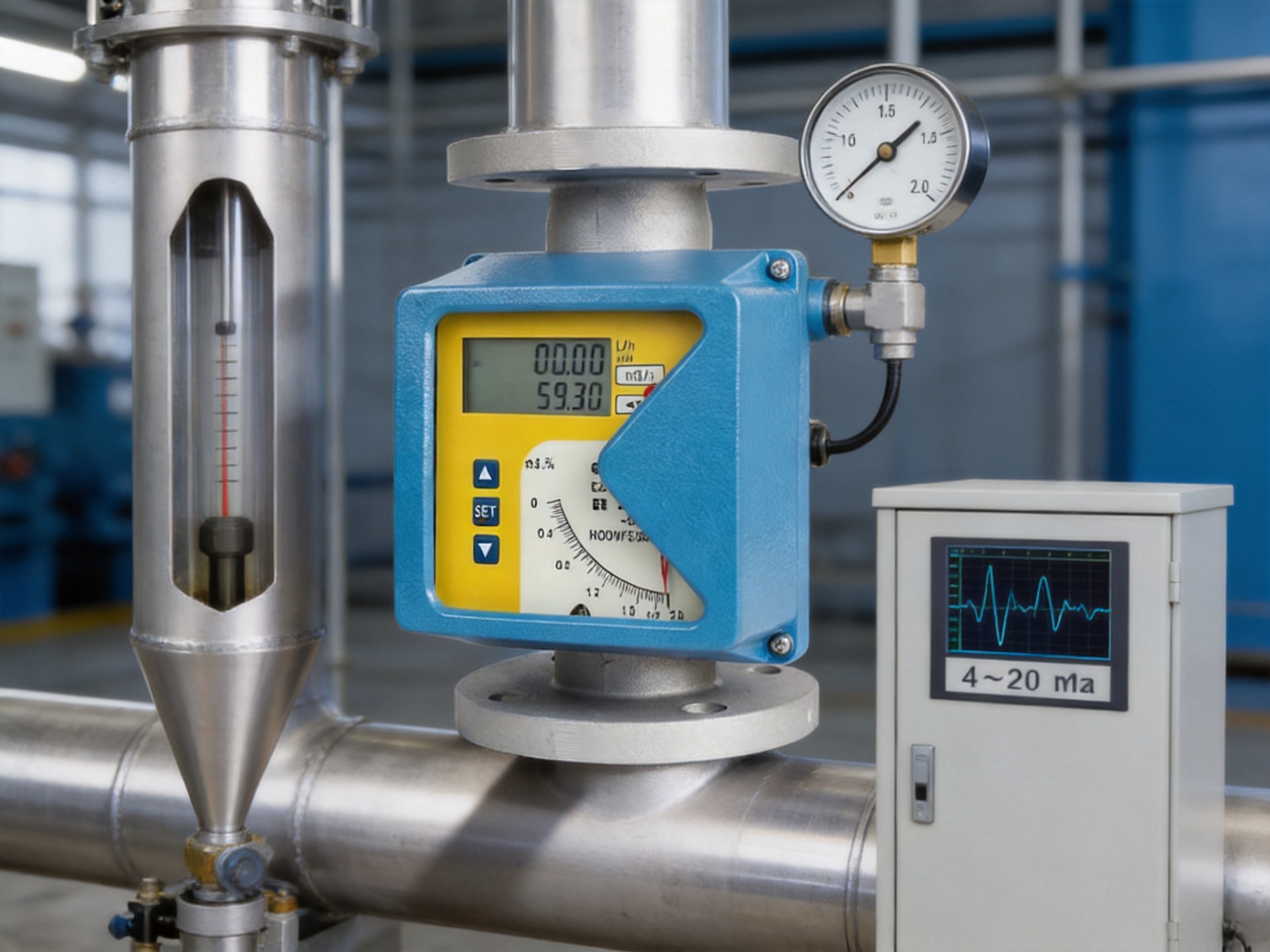
Glass tube flow meters remain attractive for low-cost, low-pressure services where direct visual observation is the main priority. They are often easy to understand and can be economical for clean water, air, and laboratory applications. However, their advantages do not extend to every industrial environment.
The XG-JF metal design offers stronger resistance to high temperature, high pressure, vibration, and mechanical damage. A glass tube may be unsuitable in a location exposed to impact, thermal shock, aggressive chemicals, or combustible process conditions. A metal tube also provides a more appropriate pressure boundary for many petrochemical, metallurgical, power, and water treatment applications.
Another difference is operational durability. A glass tube must remain clear and intact for the operator to read the float. Fouling, discoloration, condensation, or physical damage can affect visibility. The metal design uses magnetic or mechanical transfer to present the position on an external indicator, so the process fluid remains enclosed within the stronger tube assembly.
The metal construction does not mean that the instrument is immune to all process problems. Incorrect material selection, excessive scaling, severe vibration, or operation beyond the specified pressure and temperature can still reduce performance. However, within its rated service conditions, it offers a more robust alternative to a transparent glass instrument.
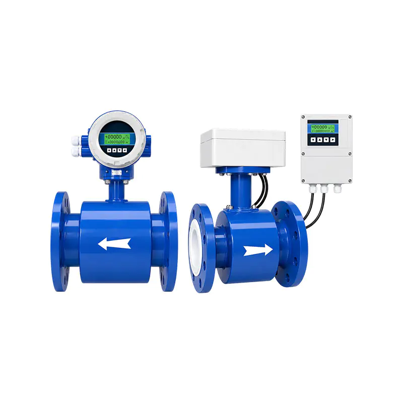
Many modern flow meters use electronic sensing technologies such as electromagnetic, vortex, ultrasonic, Coriolis, or thermal principles. These technologies can provide important advantages in the right applications, including advanced diagnostics, high accuracy, density measurement, or bidirectional measurement. They may also require more complex installation, power, signal conditioning, or process conditions.
The variable area principle is attractive when the user needs a dependable indication of a relatively stable flow without excessive complexity. The instrument can be installed without the extensive electronic infrastructure required by some advanced technologies. The local indicator is easy for operators to understand, and selected models can still provide the electronic outputs needed for remote supervision.
Compared with a differential-pressure flow meter, a float meter may offer a simple direct indication without a separate pressure transmitter, impulse tubing, or differential-pressure calculation system. Compared with some electronic meters, it can be more tolerant of power interruptions when the local mechanical indicator is selected. Compared with a thermal mass flow meter, it can measure liquids as well as gases and does not depend on thermal conductivity in the same way.
These comparisons do not mean that the metal float flow meter is the best instrument for every application. It is not generally the first choice for custody transfer, extremely high turndown, rapidly changing flow profiles, or services requiring mass flow and density measurement. Its strength lies in practical, robust, direct flow monitoring across a broad range of industrial duties.
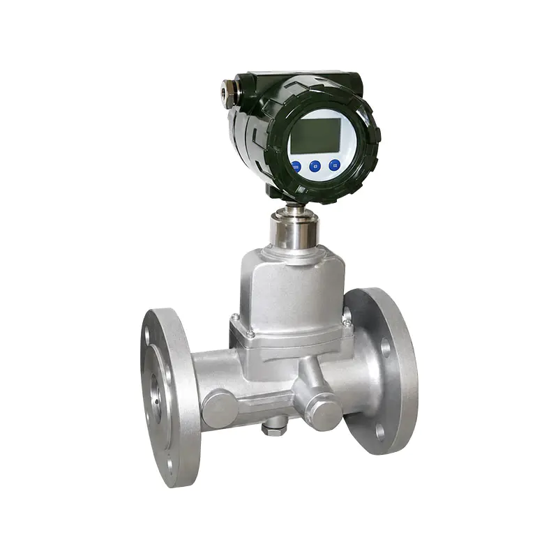
The series provides several indicator choices. The M1 configuration is a local indicator with a square housing and a mechanical pointer showing instantaneous flow. It is intended for users who value simplicity, direct reading, and operation without a complex electronic system.
The M2 configuration combines a mechanical display with an LCD that can show instantaneous and cumulative flow. This is useful when operators need both the current process condition and a running total. Battery-powered versions are available for selected configurations, allowing display operation without a continuous external supply.
The M3 configuration uses a round housing and multifunction indication. The supplied selection information also references M4-related functions for certain power, hazardous-area, and output combinations. Because the exact compatibility of indicator, power supply, alarm, communication protocol, and explosion-protection option depends on the selected model, the complete ordering code should be reviewed before purchase.
Power and output options include an 85–265 VAC, 50 Hz supply with 4–20 mA output; battery-powered operation without signal output for selected indicator types; 24 VDC two-wire supply with 4–20 mA output; and 24 VDC three- or four-wire supply with 4–20 mA output. Backlighting, relay alarms, pulse outputs, HART, and Modbus can be selected where compatible.
Upper-limit and lower-limit alarm functions can help operators identify abnormal process conditions. K1 is associated with an upper-limit alarm or one-channel pulse output, K2 with a lower-limit alarm or one-channel pulse output, and K3 with upper- and lower-limit alarms or two-channel pulse output. These functions can be valuable for pump protection, cooling-water supervision, minimum-flow monitoring, and chemical dosing control.
Backlighting improves readability in dark equipment rooms or outdoor enclosures. HART communication can support configuration and diagnostic access in compatible control architectures, while Modbus can simplify connection to digital monitoring systems. These options extend the usefulness of the instrument without changing its basic, intuitive variable area operating principle.
The selection guide identifies several structural codes. Code 0 represents bottom inlet and top outlet flow, which is the conventional vertical arrangement. Code 1 represents bottom inlet with horizontal outlet from the top. Code 2 represents horizontal inlet from the bottom with horizontal outlet from the top. Codes 3R and 3L represent right-to-left and left-to-right flow arrangements respectively.
These options are intended to accommodate actual piping and equipment layouts. A process engineer may need the meter to fit between existing valves, connect to a side-entry panel, or align with a compact skid. Selecting the correct structure at the beginning is preferable to forcing the piping into an unsuitable arrangement after delivery.
The standard installation requirement remains important. The instrument must be installed in the orientation specified for the selected structure, and the flow direction must match the arrow or connection designation. For the conventional version, the medium flows from bottom to top. The meter should not be installed horizontally or upside down when the selected model requires vertical installation.
Strong vibration should be avoided. Appropriate straight pipe sections should be maintained before and after the meter where possible, even though the series has relatively low straight-run requirements compared with some other flow technologies. Valves should be positioned and operated in a way that minimizes sudden disturbances. The pipeline should be adequately supported so that the meter does not carry excessive mechanical stress.
Before installation, verify the nominal size, process connection, flow direction, material compatibility, pressure rating, temperature rating, and indicator power requirements. Confirm that the operating flow falls within the calibrated range and that the medium density and viscosity correspond to the supplied calibration.
Install a filter or strainer when particles may be present. Make sure that the filter is sized for the required flow and that it can be maintained safely. For liquids, remove trapped air where air pockets could disturb the float. For gases, consider pressure and temperature changes that may alter density between the upstream piping and the measuring tube.
After installation, open valves gradually. Sudden flow surges can cause the float to move violently and may damage the indicator or disturb the process. Check the local reading against a reference condition where practical. For electronic versions, verify the loop current, alarm set points, communication address, and display scaling before placing the instrument into routine service.
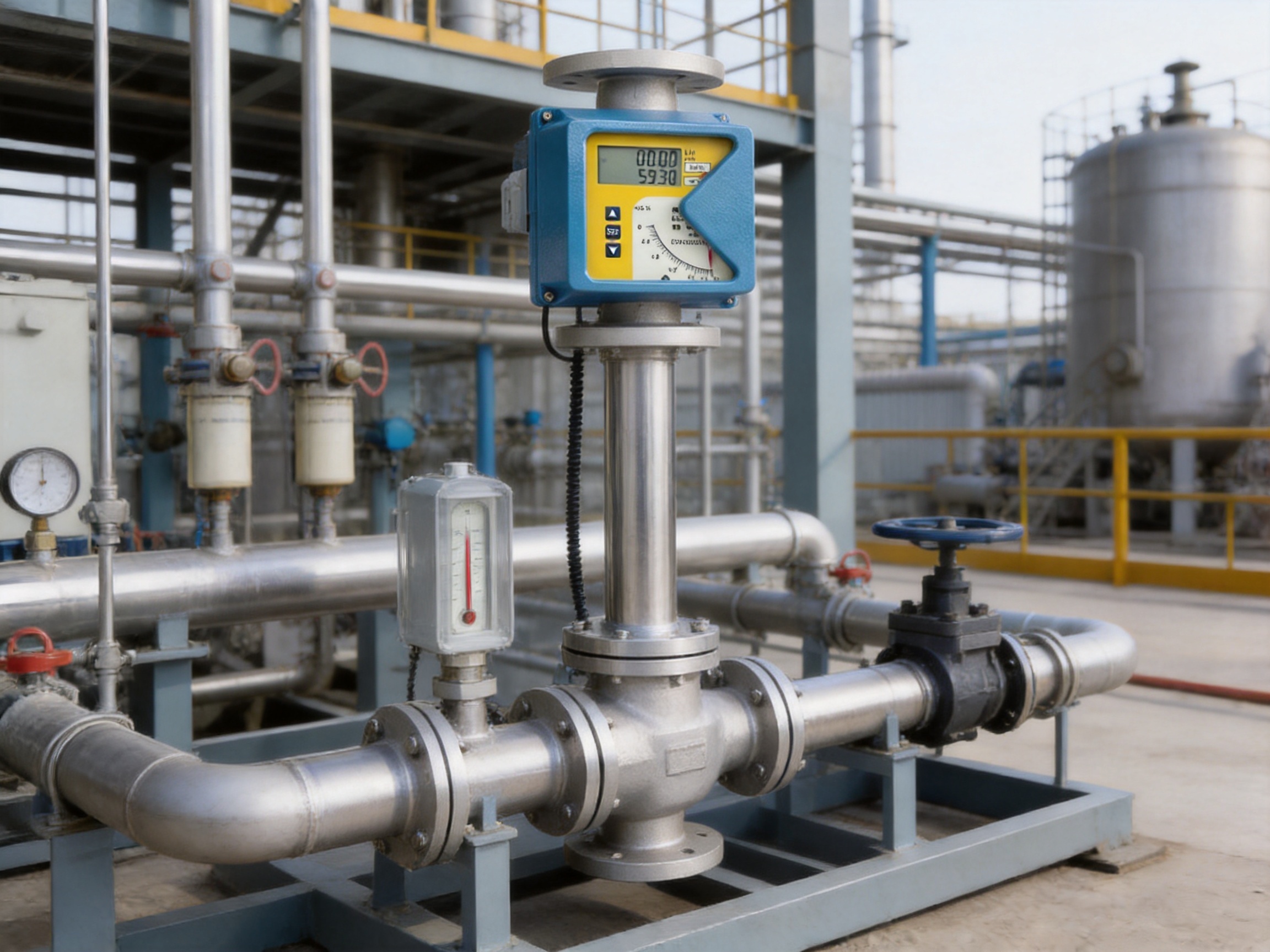
Petrochemical plants use flow measurement for process fluids, solvents, purge gases, seal systems, cooling services, and auxiliary chemical streams. The metal float design is suitable for applications where a glass tube would be vulnerable to high pressure, elevated temperature, vibration, or mechanical damage. Material selection is particularly important for solvents, corrosive compounds, and mixtures whose composition changes during operation.
Local indication can help field operators verify that a purge, seal, or cooling stream is active. Remote output can send the same information to a distributed control system or plant monitoring platform. Alarm options can be used to identify a loss of minimum flow or a high-flow condition that may indicate a valve problem, leak, or control fault.
Water and wastewater facilities require flow monitoring for raw water, purified water, sewage, air scour, chemical dosing, sampling systems, and sludge-related auxiliary services. The instrument can be specified for clean water and selected media containing small amounts of impurities, provided that excessive particles, scaling, and viscosity are controlled.
In chemical dosing systems, a local flow display gives operators immediate confirmation that the injection line is operating. In larger installations, the 4–20 mA output can be used for proportional control or alarm generation. Corrosion-resistant materials may be selected when the medium contains acids, alkalis, oxidizing agents, or other aggressive chemicals.
Steel and metallurgical plants contain many services exposed to heat, vibration, dust, and demanding operating conditions. The series can be used for cooling water, process gas, instrument air, purge gas, and auxiliary media. Metal construction is beneficial in areas where equipment may be exposed to mechanical impact or where high process temperatures make glass unsuitable.
For cooling circuits, minimum-flow monitoring is especially important. A loss of cooling flow can result in equipment overheating, reduced production stability, or damage to heat exchangers and furnace-related components. An indicator with alarm output can provide an additional layer of operational awareness.
Power plants and energy facilities use flow meters for steam-related auxiliary services, compressed air, cooling water, water treatment, fuel support systems, and various utility streams. The high-temperature and high-pressure options allow the instrument to be considered for selected services where ordinary glass meters cannot be used.
As with every flow measurement device, the exact application must be evaluated against pressure, temperature, fluid phase, density, viscosity, and required accuracy. The metal float flow meter is particularly appropriate for monitoring auxiliary flows and utility services rather than replacing specialized custody-transfer or high-performance steam measurement systems.
The performance of a flow meter depends not only on its published specifications but also on how consistently it is manufactured. Dimensional accuracy of the measuring tube, float geometry, magnetic coupling, indicator mechanism, welding, surface treatment, sealing, calibration, and final inspection all influence field reliability.
Xinguo Group operates as a diversified industrial manufacturer with businesses covering instrumentation, alloy materials, cables, and precious-metal products. This industrial scope is relevant to metal float flow meters because the company’s capabilities extend beyond final assembly. Control of material selection, component processing, fabrication, and inspection can help maintain consistency across the product lifecycle.
The group reports a land area of more than 150 mu, a construction area of approximately 60,000 square meters, and a workforce of nearly 300 people, including more than 50 professional technicians, senior technical experts, engineers, and assistant engineers. These resources support product development, process improvement, production planning, technical service, and quality control.
Manufacturing begins with engineering review and material selection. The process medium, pressure, temperature, flow range, connection size, indicator type, and communication requirements must be translated into a practical instrument configuration. Materials such as stainless steel, titanium alloy, or PTFE-related options are selected according to the application rather than treated as interchangeable choices.
Fabrication of the measuring tube requires control of geometry and surface condition. The float must move smoothly through the measuring passage without excessive friction or interference. Welded or machined parts must maintain the required pressure integrity. Process connections must be aligned accurately so that installation does not introduce unnecessary mechanical stress.
The magnetic coupling and indication system require careful assembly. Because the float position inside the tube is transferred to the external indicator, coupling sensitivity and repeatability affect the reading. The indicator mechanism must be assembled so that pointer movement, LCD scaling, alarm switching, and electronic output correspond to the calibrated flow position.
Calibration is a central manufacturing step. The instrument should be tested with appropriate reference media or calibrated conditions, and the output should be checked across relevant points in the measuring range. Electronic versions require verification of the 4–20 mA relationship, display values, alarm thresholds, power supply behavior, and communication functions where specified.
The company reports quality management certifications including ISO9001, ISO14001, and GB/T28001. These systems address quality management, environmental management, and occupational health and safety management. Certification does not replace application-specific engineering, but it indicates that the manufacturer has established formal management processes for production and organizational control.
The group also states that its products are developed and manufactured to meet IEC international standards as well as national and industrial specifications where applicable. For buyers, the important practical step is to request the relevant product documentation, inspection records, calibration information, material certificates, and certification details for the exact model being purchased.
Industrial flow measurement rarely follows a single standard pattern. A customer may require a special process connection, a corrosive wetted material, a high-pressure tube, a jacketed structure, a remote transmission function, or a particular communication protocol. Engineering resources are therefore important when adapting a base product to a real installation.
The group’s instrumentation, alloy, cable, and related manufacturing activities create a broad technical foundation for product development. The XG-JF Series reflects this approach through its range of measuring tube structures, wetted materials, indicator arrangements, power supplies, alarms, and communication choices.
Customization should still be controlled carefully. Every change to material, temperature, pressure, lining, float, indicator, or connection can affect calibration and operating limits. A responsible selection process documents the complete application and verifies that the final combination is technically compatible.
The XG-JF Series has a relatively simple internal principle and few moving parts. This can reduce the number of components that may fail in routine service. The external indicator and non-contact coupling arrangement also help separate the display mechanism from the process fluid.
Routine maintenance should include checking for abnormal pointer movement, unstable readings, external leakage, corrosion, vibration, loose connections, and signs of process contamination. Electronic versions should also be checked for display operation, output stability, alarm performance, power-supply condition, and communication status.
If the reading becomes inaccurate or the float appears to stick, the cause may be contamination, scaling, excessive viscosity, incorrect installation, gas entrainment, density change, damaged magnetic coupling, or operation outside the calibrated range. The instrument should be isolated and depressurized before inspection. Maintenance personnel must follow the site’s lockout, isolation, and hazardous-area procedures.
Cleaning should be performed using methods and materials compatible with the wetted components. Abrasive tools or aggressive solvents may damage the measuring tube, lining, float, or seals. A filter upstream can reduce the frequency of cleaning and protect the float from particles.
For electronic models, calibration verification should be scheduled according to the criticality of the application, process stability, regulatory requirements, and site quality program. A stable utility service may require less frequent verification than a safety-related or high-value process measurement.
Selection begins with the medium. Identify whether the service is liquid, gas, or vapor, and provide the chemical name, concentration, density, viscosity, solids content, and tendency to scale. For gases, specify normal and maximum pressure and temperature because gas density changes significantly with operating conditions.
Next, define the normal, minimum, maximum, and possible upset flow rates. The selected range should not merely cover the maximum. It should provide useful resolution at the normal operating point. If the flow varies widely, the 10:1 flow ratio may be helpful, but the final range must be confirmed against the specific fluid and tube design.
Pressure and temperature must be considered together. A model that is acceptable at moderate temperature may have a lower allowable pressure at elevated temperature. High-temperature, high-pressure, jacketed, and PTFE-related configurations have different limitations.
Specify the pipe size and connection arrangement. Choose the measuring tube structure that matches the actual installation. Confirm the inlet and outlet direction, available straight pipe, access for reading, and space for removing or servicing the instrument.
Choose the indicator according to the operating philosophy. Select a mechanical local indicator when direct reading is sufficient. Select an LCD or multifunction indicator when cumulative flow, backlighting, or advanced display functions are needed. Add 4–20 mA output, relay alarms, pulse output, HART, or Modbus when integration with a control or monitoring system is required.
For hazardous locations, determine whether intrinsically safe or flameproof construction is required. The supplied information identifies intrinsically safe Ex ia options for selected indicators and flameproof Ex d construction for compatible round-housing configurations. Hazardous-area selection must be based on the actual site classification and the complete equipment certification.

Yes. The XG-JF Series is designed for liquid, gas, and vapor flow measurement. The selected scale and float must match the physical properties and operating conditions of the medium. Gas applications require particular attention to pressure and temperature because changes in density influence the reading.
It can handle small amounts of particulate impurities, but it is not recommended for media with large particles, high solids content, severe scaling, or viscosity beyond the specified limit. Excessive contamination can cause the float to stick and produce an inaccurate reading. Pre-filtration is recommended when particles may be present.
The basic local mechanical indicator does not require an external power supply. It provides a direct on-site reading. Models with 4–20 mA transmission, electronic display, alarm functions, or communication interfaces require the applicable external power supply or battery configuration.
The conventional structure must be installed vertically, with flow from bottom to top. Other structural versions are available for selected horizontal or side-entry arrangements. The installation orientation must match the structure ordered. Installing a vertical model horizontally or upside down can affect float movement and measurement accuracy.
The series does not have especially demanding straight-pipe requirements compared with some other flow technologies. Nevertheless, stable flow conditions are desirable. Avoid placing the meter immediately after severe turbulence, a partially open valve, a pump discharge, or a sharp piping transition. Follow the manufacturer’s installation guidance for the selected model.
A metal float meter is preferred when the application involves high temperature, high pressure, vibration, mechanical impact, corrosive media, or potentially hazardous industrial conditions. A glass tube meter may be suitable for clean, low-pressure, low-temperature services where low cost and direct visibility are more important than ruggedness.
Standard configurations are listed for approximately -80 to 200°C. PTFE-related configurations are listed for approximately 0 to 85°C, and high-temperature types are available for temperatures greater than 400°C. The exact limit depends on the measuring tube, lining, seals, indicator, process connection, and selected option.
Standard ratings are listed as up to 4.0 MPa for DN15 to DN50 and 1.6 MPa for DN80 to DN200. Special high-pressure versions are listed as up to 25 MPa for DN15 to DN50 and 16 MPa for DN80 to DN200. Jacketed versions are listed at 1.6 MPa. The final allowable pressure must be confirmed for the exact model and temperature.
Yes. Compatible configurations can provide 4–20 mA output, relay alarm functions, pulse output, HART communication, or Modbus communication. Power options include 24 VDC and 85–265 VAC configurations, while selected versions can operate on battery power for local display without signal transmission.
Check for excessive vibration, air or gas entrainment in a liquid line, rapidly changing flow, incorrect installation orientation, upstream turbulence, contamination, scaling, and operation outside the calibrated range. The instrument should be isolated and depressurized before opening or cleaning. If the problem continues, the instrument should be recalibrated or inspected by qualified personnel.
The series is primarily intended for industrial monitoring, process control, and utility measurement. It should not be selected for custody transfer or other regulated measurement duties unless the exact model has the required approvals, accuracy, calibration documentation, and legal metrology certification.
Provide the medium, minimum and maximum flow, normal flow, pressure, temperature, viscosity, density, pipe size, connection requirements, material compatibility, installation orientation, hazardous-area classification, and output requirements. The manufacturer can then determine the appropriate measuring tube, wetted material, float, indicator, power supply, and optional communication functions.
The XG-JF Series Metal Float Flow Meter combines the simplicity of variable area measurement with the strength and adaptability required for industrial service. Its metal tube construction provides a practical alternative to glass instruments in high-temperature, high-pressure, corrosive, vibrating, and mechanically demanding environments. Its application range includes liquids, gases, and vapors, with configurations for low-flow services, utility systems, process monitoring, and auxiliary equipment protection.
Its principal advantages include direct local indication, optional power-free operation, compact construction, a broad flow ratio, multiple measuring tube arrangements, material choices for demanding media, and electronic options for remote monitoring. Mechanical pointer indicators suit straightforward field operation, while LCD, 4–20 mA, alarm, pulse, HART, and Modbus options support modern control architectures.
The product is also supported by the manufacturing resources of Xinguo Group Co., Ltd. The company’s experience in industrial instrumentation, alloy materials, cables, and related products provides a foundation for material control, product development, fabrication, calibration, and quality assurance. Its reported ISO9001, ISO14001, and GB/T28001 management certifications further demonstrate an organized approach to quality, environmental responsibility, and occupational safety.
Proper selection remains essential. The best results are achieved when the user supplies complete process information, chooses the correct structure and material, respects pressure and temperature limits, installs the instrument in the required orientation, and protects the float from excessive particles and scaling. When these conditions are met, the metal float flow meter offers a dependable, maintainable, and cost-effective solution for a wide range of industrial flow measurement duties.
1. Xinguo Group Co., Ltd., XG-JF Series Metal Float Flow Meter Product Information and Selection Guide.
2. Xinguo Group Co., Ltd., Product Data for Industrial Temperature, Pressure, Flow, and Level Instruments.
3. International Electrotechnical Commission, General Principles for Industrial Measurement and Control Equipment.
4. ISO 9001, Quality Management Systems — Requirements.
5. ISO 14001, Environmental Management Systems — Requirements with Guidance for Use.
6. GB/T 28001, Occupational Health and Safety Management System Requirements.
7. General industrial practice for variable area flow measurement, float selection, process compatibility, installation, and calibration.



 INQUIRY
 English
 عربى
 русский
 中文简体