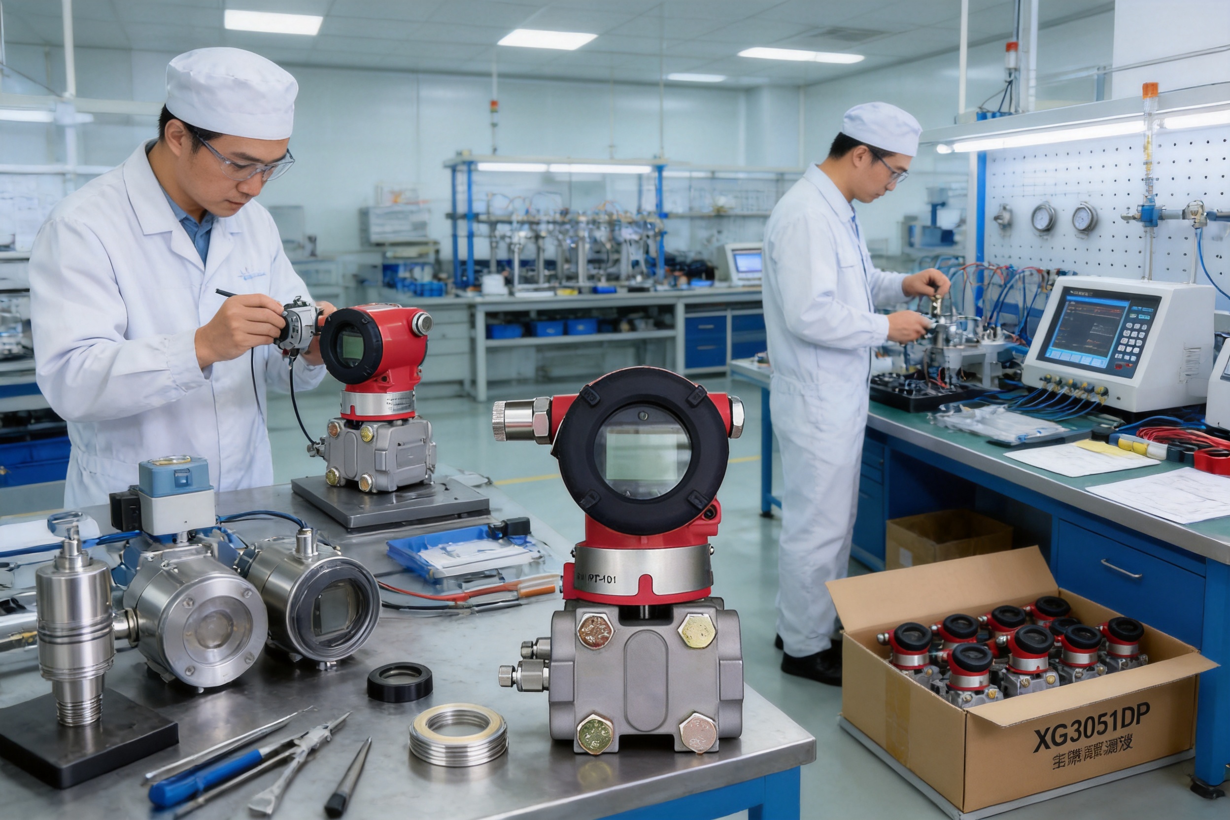
Differential pressure measurement is one of the most important functions in modern process instrumentation. It supports flow monitoring, liquid-level measurement, filter condition assessment, furnace draft control, and pressure-difference supervision across industrial pipelines. In demanding environments, a transmitter must do more than convert pressure into an electrical signal. It must provide dependable accuracy, stable operation, flexible configuration, material compatibility, convenient installation, and reliable communication with automation systems.
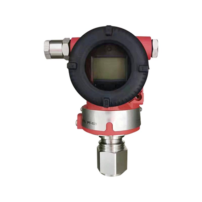
The XG3051DP Differential Pressure Transmitter is designed for these requirements. Based on a capacitive sensing principle, it converts the differential pressure between its high-pressure and low-pressure sides into a standard two-wire 4–20 mA signal, with optional HART digital communication. Its configurable range, multiple diaphragm materials, selectable output functions, broad process compatibility, and robust housing make it suitable for petrochemical, power-generation, water-treatment, metallurgy, paper, and general process industries.
Rather than being limited to one measurement task, the XG3051DP is a versatile platform. It can measure differential pressure directly and can also be applied to flow measurement, closed-vessel liquid-level measurement, filter pressure-drop monitoring, pipeline pressure-difference measurement, and furnace negative-pressure supervision. When used for flow applications, its square-root output function can be activated so that the current signal corresponds more closely to the calculated flow relationship.
This article explains the operating principle, main advantages, performance characteristics, configuration options, application value, manufacturing strengths, installation considerations, maintenance requirements, and selection guidance for the XG3051DP Differential Pressure Transmitter.
The XG3051DP is an intelligent differential pressure transmitter belonging to the domestically produced 3051-style capacitive transmitter family. Its sensing capsule detects the pressure difference between two process connections. Internal electronic circuitry then processes the sensor signal and generates a proportional 4–20 mA DC output. An optional HART communication function provides digital access to configuration, diagnosis, calibration, range adjustment, damping, output mode, and other operating parameters.
The transmitter is suitable for applications in which the measured variable is the difference between two pressures. The positive and negative pressure ports may be connected to two points on a process line, to the upstream and downstream sides of a filter, or to different points in a closed vessel. The pressure relationship between these ports determines the output signal.
Its basic design supports a broad range of industrial requirements. Range codes extend from very low differential pressure measurements of approximately 0.1 kPa span to high differential pressure applications with spans up to 2,000 kPa. Multiple working-pressure ratings are available, including 16 MPa, 25 MPa, and 40 MPa versions, depending on the selected configuration. This allows the sensing range and pressure-resistance capability to be selected independently according to the process conditions.
The transmitter uses a 316L stainless-steel measuring capsule as a standard construction. Depending on the chemical properties of the measured medium, the diaphragm can be selected in 316L stainless steel, Hastelloy C, gold-plated 316L stainless steel, FEP-coated 316L stainless steel, or tantalum. Fluorinated oil, silicone oil, and special oil-free configurations are also available for different process and cleanliness requirements.
The housing is designed for industrial service and provides IP67 protection. The electrical connection may use an M20 × 1.5 cable entry or a 1/2-14 NPT cable entry, depending on the selected housing option. A local LCD or OLED display can be specified for on-site indication and adjustment.
The XG3051DP uses a capacitive sensing principle. The process pressure applied to the high-pressure and low-pressure sides acts on the sensing diaphragm through the pressure transmission structure. The differential pressure causes a small mechanical displacement in the sensing element. This displacement changes the capacitance of the sensor, and the electronic module converts the capacitance change into a calibrated electrical output.
For a linear output setting, the transmitter produces a 4–20 mA signal proportional to the configured differential-pressure range. At the lower range value, the output is nominally 4 mA. At the upper range value, the output is nominally 20 mA. The range may be configured within the limits of the selected span code, provided that the calibrated span is not less than the specified minimum span.
For flow applications, the transmitter can use a square-root output function. Differential pressure generated by many primary flow devices is proportional to the square of flow. The square-root function compensates for this relationship so that the transmitter output more closely represents flow. This function can be selected as a special configuration or activated through compatible configuration procedures, depending on the ordered version.
When HART communication is included, the analog current signal continues to provide the main process value while digital communication is superimposed on the two-wire loop. A suitable loop resistance, generally within the specified digital communication range, is required for reliable communication. A 250 Ω series resistance is commonly used in a conventional HART loop, subject to the requirements of the control system and power supply.
The transmitter is not restricted to a single process parameter. Its primary function is differential-pressure measurement, but the same measurement principle enables several important industrial applications. It can be connected across an orifice plate, venturi tube, flow nozzle, filter, heat exchanger, or other pressure-producing device. It can also be connected to the upper and lower pressure points of a closed tank to calculate liquid level.
This flexibility can reduce the number of different transmitter platforms required in a plant. Standardizing on one transmitter family simplifies spare-parts management, training, commissioning, and maintenance procedures. It also allows plant engineers to become familiar with a consistent set of menus, electrical connections, process interfaces, and diagnostic methods.
The standard two-wire 4–20 mA signal remains one of the most widely accepted industrial instrumentation signals. It is compatible with distributed control systems, programmable logic controllers, safety-related monitoring systems, data-acquisition units, and conventional panel instruments. The XG3051DP combines this established signal with optional HART digital communication.
HART communication provides access to information that is not available through the analog signal alone. Operators or maintenance technicians can read the configured range, change damping, perform zero and span adjustments, select linear or square-root output, review diagnostic conditions, and support commissioning without physically removing the transmitter from the installation.
The combination of analog compatibility and digital configuration is a practical advantage over devices that require a proprietary communication system. It permits gradual modernization of existing plants while preserving compatibility with established control wiring.
The available range codes cover very low, medium, and high differential pressures. Lower range versions are suitable for air, gas, furnace draft, ventilation, and low-pressure flow applications. Medium ranges support general pipeline flow, filter monitoring, and tank-level measurement. Higher ranges are suitable for process systems in which a substantial differential pressure may occur or where the transmitter must tolerate high static pressure.
The transmitter allows the range to be adjusted within the upper and lower limits of the selected range code. Selecting a range code with the lowest practical turndown ratio generally improves measurement performance. This gives users a useful balance between application flexibility and accuracy.
Material selection is essential when the transmitter is exposed to corrosive, high-chloride, acidic, alkaline, hygienic, or oxygen-related media. The standard 316L stainless-steel diaphragm is appropriate for many general industrial services. For more aggressive media, Hastelloy C, tantalum, gold-plated stainless steel, or FEP-coated stainless steel may be selected.
The material options help users match the transmitter to the actual process chemistry rather than relying on one universal construction. A compatible diaphragm can extend service life, reduce the risk of corrosion-related drift, and protect measurement reliability. Seal options including NBR, FKM, and PTFE further support application-specific chemical and temperature requirements.
The transmitter is designed for an ambient temperature range of approximately −40 to 85 °C in standard configurations. Versions with certain displays or fluororubber seals may have specific temperature restrictions. The instrument also provides protection against static pressure and overpressure within the specified ratings.
Static pressure capability is important because differential-pressure transmitters are often installed in systems where both sides are exposed to a high line pressure. The XG3051DP can be specified with rated working pressures of 16 MPa, 25 MPa, or 40 MPa. The proof-pressure capability can reach 1.5 times the rated pressure when applied simultaneously to both sides, subject to the product configuration and operating instructions.
The output alarm mode can be selected according to the needs of the control system. The low-alarm mode produces a minimum current of approximately 3.7 mA, while the high-alarm mode produces a maximum current of approximately 21 mA. A no-alarm or hold mode can maintain the valid current value present before a fault.
The default high-alarm mode offers a clear abnormal indication in many process-control applications. However, the ability to select another mode allows the transmitter to be coordinated with plant alarm philosophy, control-system logic, and process safety requirements.
The amplifier damping constant is approximately 0.1 seconds, while the sensor time constant typically ranges from 0.1 to 2 seconds depending on span and turndown. An additional adjustable time constant from approximately 0.1 to 60 seconds can be used to stabilize the signal where the process contains pulsation, turbulence, vibration, or rapidly changing pressure.
Damping should be selected carefully. A longer damping time can reduce output fluctuation, but excessive damping may delay the response to a genuine process change. The XG3051DP allows the user to balance stability and responsiveness according to the application.
The aluminum-alloy housing with protective coating provides a practical combination of low weight and environmental resistance. Stainless-steel housing options are available where a more corrosion-resistant enclosure is preferred. The IP67 protection class helps protect the internal electronics against dust and temporary water exposure when the cable entries, covers, and seals are correctly installed.
The approximate transmitter weight is 3.3 kg excluding the display, mounting bracket, and process accessories. Its compact industrial construction supports both direct and bracket-mounted installation.
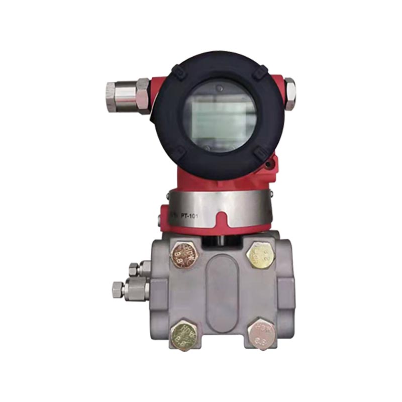
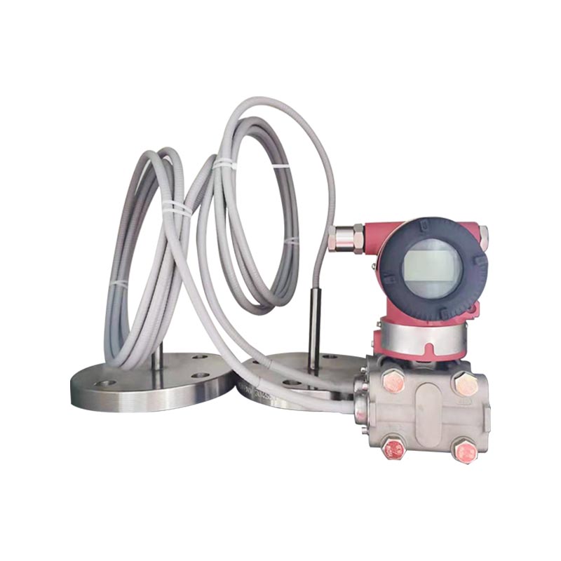
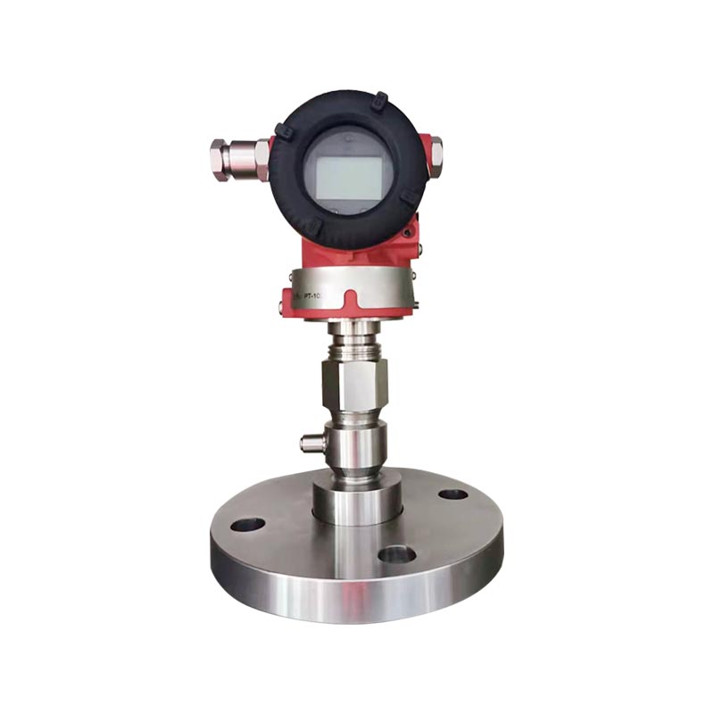
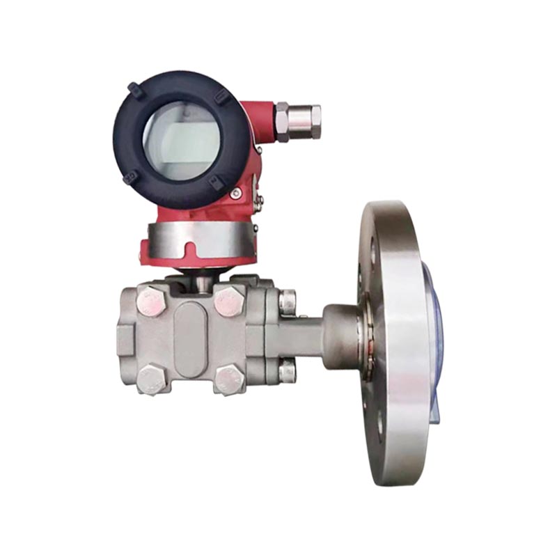
XG3051DP Differential pressure transmitter
The reference accuracy for range adjustment, including zero-based linearity, hysteresis, and repeatability, can reach ±0.075 percent for the applicable configuration. Higher-accuracy versions with basic errors of approximately ±0.05 percent are also included in the model-selection system. Other configurations provide ±0.1 percent performance where application requirements and budget considerations favor a standard version.
When the turndown ratio exceeds 10, the accuracy is expressed as ±(0.0075 × TD) percent for the relevant reference condition, where TD is the maximum span divided by the adjusted span. This relationship illustrates why selecting an appropriate range code is important. A transmitter should not be configured at an unnecessarily small span when a more suitable range code is available.
For square-root output, the reference accuracy is approximately 1.5 times the corresponding linear reference accuracy. This reflects the mathematical transformation used to convert differential pressure into a flow-related output and should be considered when preparing an application accuracy calculation.
Ambient temperature can influence the measurement of any pressure transmitter. The XG3051DP provides specified temperature-effect values according to the selected span code. For span code A, the total effect from −20 to 65 °C is expressed as ±(0.45 × TD + 0.25) percent of span. For span code B, the corresponding expression is ±(0.30 × TD + 0.20) percent of span.
For span codes C, D, and E, the total effect from −20 to 65 °C is expressed as ±(0.20 × TD + 0.10) percent of span. The same stated expressions apply in the extended temperature intervals of −40 to −20 °C and 65 to 85 °C according to the supplied technical data. An out-of-range effect of approximately ±0.075 percent of span is also specified.
Static pressure affects the two sides of a differential-pressure sensor when the line pressure is high. The stated static-pressure effect depends on the span code and the pressure level. For span code A, the effect is approximately ±(0.15 percent URL + 0.10 percent span) per 4 MPa. For span code B, it is approximately ±(0.10 percent URL + 0.075 percent span) per 16 MPa.
For span codes C, D, and E, the effect is approximately ±(0.05 percent URL + 0.05 percent span) per 16 MPa. These values should be included in the instrumentation error budget when a low differential pressure is measured on a high-static-pressure pipeline.
Overpressure can occur when one pressure port is exposed to a higher pressure than the other, such as during incorrect valve sequencing or a sudden process upset. The stated overpressure effect is approximately ±0.2 percent of span per 4 MPa for span code A, ±0.2 percent of span per 16 MPa for span code B, and ±0.1 percent of span per 16 MPa for span codes C, D, and E.
Long-term stability is specified at approximately ±0.5 percent of span per year for span code A, ±0.2 percent of span per year for span code B, and ±0.1 percent of span per year for span codes C, D, and E. Actual field performance depends on installation quality, temperature cycling, pressure pulsation, corrosion, vibration, and calibration practices.
The standard power supply is 24 VDC, with an operating range generally extending from 12 to 42 VDC. Versions with a backlit LCD may require a higher minimum supply voltage of approximately 15 VDC. The maximum supply voltage is 42 VDC.
The permissible loop load follows the relationship R ≤ (Us − 12 V) / Imax, with the applicable current units and circuit conditions considered during system design. For reliable HART communication, the digital communication load range is approximately 250 to 600 Ω. The power supply, loop resistance, barrier, isolator, cable length, and control-system input must be assessed together.
| Parameter | Typical or Available Specification | Application Significance |
|---|---|---|
| Output | Two-wire, 4–20 mA DC; optional HART | Compatible with DCS, PLC, and digital configuration |
| Reference accuracy | Up to ±0.075%; selected versions approximately ±0.05% | Supports process control and monitoring accuracy |
| Ambient temperature | Approximately −40 to 85 °C | Suitable for many indoor and outdoor installations |
| Rated working pressure | 16 MPa, 25 MPa, or 40 MPa | Allows selection for high-static-pressure service |
| Process connection | 1/4 inch NPT and M10 internal threads | Supports common impulse-line and accessory arrangements |
| Housing protection | IP67 | Helps protect electronics in industrial environments |
| Adjustable damping | Approximately 0.1–60 seconds | Balances signal stability and response time |
| Display options | No display, backlit LCD, or OLED | Supports local viewing and commissioning |
In petrochemical plants, differential pressure transmitters are used for reactor level, tank level, pipeline flow, filter pressure drop, and vessel pressure monitoring. A closed tank may contain vapor pressure above the liquid, making direct level measurement based only on liquid pressure unsuitable. By connecting the high-pressure and low-pressure sides correctly, the XG3051DP can compensate for vessel vapor pressure and measure the hydrostatic differential associated with liquid level.
Filter monitoring is another important application. As a filter becomes blocked, the pressure difference between its inlet and outlet increases. The transmitter can provide a continuous signal to a control system, allowing operators to establish an alarm or maintenance threshold before the filter causes an unacceptable reduction in process capacity.
Where corrosive chemicals or high-chloride media are present, the diaphragm and seal materials should be selected carefully. Hastelloy C, tantalum, gold-plated stainless steel, FEP-coated stainless steel, FKM, and PTFE options provide additional flexibility beyond a basic 316L configuration.
Power plants require dependable measurement of steam, water, air, and combustion-related pressures. The XG3051DP can be applied to boiler and turbine auxiliary systems, steam and water flow, furnace negative pressure, vessel liquid level, and filter differential pressure.
Furnace draft measurement often involves very low differential pressures, so a suitable low-range span code is important. Stable impulse-line routing, protection from condensation, and appropriate damping are necessary to prevent false fluctuations. In water and steam applications, impulse-line arrangement and temperature management are particularly important because condensation or unequal temperature effects can introduce measurement error.
For high-pressure water or steam systems, the rated working pressure must be selected according to the maximum static pressure, not merely the differential-pressure span. This is one of the main reasons the available 16, 25, and 40 MPa ratings are useful in power-generation applications.
Water-treatment systems use differential pressure measurement to monitor pipeline flow, filter condition, tank level, and process performance. Filtration units commonly depend on pressure-drop measurement to identify clogging. Level measurement is used in chemical dosing tanks, settling tanks, storage vessels, and treatment basins.
Wastewater may contain suspended solids, corrosive substances, biological material, and changing chemical concentrations. Proper impulse-line design is therefore essential. The transmitter itself should be specified with wetted materials and seals compatible with the process. Regular inspection helps prevent impulse-line blockage and fluid accumulation, which are common causes of zero drift.
Metallurgical processes include high temperatures, dust, corrosive gases, slurry, and pressure fluctuations. The transmitter can measure fluid pressure difference, process pipeline flow, and vessel liquid level when installed with suitable impulse piping, cooling arrangements, and protective accessories.
In dusty or vibrating areas, the IP67 housing and robust mounting arrangement help protect the instrument. However, the transmitter should not be treated as a substitute for proper environmental engineering. Cable entries must be sealed, the mounting bracket must be rigid, and the impulse lines must be supported to prevent mechanical strain on the process connection.
Paper mills use differential pressure measurement for pulp level, filter pressure drop, process flow, and other utility systems. Pulp and fiber-containing media can create deposits or block narrow impulse lines. The selected process connection, flushing arrangement, and impulse-line diameter should therefore be considered together.
Where the medium is chemically aggressive, material selection becomes especially important. Hastelloy, tantalum, coated diaphragm, or suitable seal materials may provide better resistance than standard stainless steel, depending on the exact composition and temperature of the process fluid.
The performance of a pressure transmitter depends not only on its design but also on the consistency of manufacturing. The manufacturer behind the XG3051DP is an industrial instrumentation group with activities covering temperature instruments, pressure instruments, flow meters, level instruments, alloy materials, cables, and related products. This broad product structure supports a more integrated understanding of process measurement and industrial materials.
The group was established in 1997 and operates from Tianchang, Anhui Province, China. Its organization includes specialist companies involved in instruments, alloys, cables, and precious-metal materials. The group has a registered capital of RMB 118 million, a land area exceeding 150 mu, a construction area of approximately 60,000 square meters, and a workforce of nearly 300 people, including more than 50 professional technical personnel and engineering specialists.
This manufacturing scale provides several practical advantages. It supports dedicated production areas, specialized equipment, internal technical coordination, and the ability to manage multiple stages of product development. Pressure transmitters require the coordinated control of mechanical machining, diaphragm preparation, electronic assembly, sealing, calibration, enclosure production, and final inspection. An established industrial organization can provide the resources required to control these stages systematically.
The group has obtained ISO9001 Quality Management System certification, ISO14001 Environmental Management System certification, and GB/T28001 Occupational Health and Safety Management System certification. These systems provide structured methods for document control, process management, inspection, corrective action, environmental responsibility, and workplace safety.
For a pressure transmitter, a quality system is valuable because performance depends on repeatable processes. The sensing capsule, electronic module, housing, seals, process flange, and accessories must be assembled according to controlled procedures. Calibration records and inspection results should be traceable to the relevant product and production batch.
Environmental and occupational safety systems also contribute to responsible manufacturing. They encourage controlled use of materials, improved waste management, risk assessment, and safer production practices. These elements are increasingly important to international customers evaluating the complete supply chain rather than only the product datasheet.
The group maintains research and development resources supported by technical experts, senior engineers, engineers, and assistant engineers. This technical structure is important for products such as intelligent transmitters because development involves both mechanical and electronic disciplines.
Research and development work may include sensor optimization, signal processing, temperature compensation, enclosure improvement, process-material evaluation, communication functions, and application-specific configuration. A manufacturer that also produces alloy materials and industrial cables can draw on broader internal knowledge when selecting materials and designing complete instrumentation solutions.
The manufacturing organization uses advanced equipment, modern production techniques, and inspection procedures throughout the production cycle. For the XG3051DP, important production-control activities include dimensional inspection of process parts, verification of diaphragm and seal materials, electronic testing, pressure testing, insulation and wiring inspection, calibration, and final functional verification.
Calibration is particularly important. A transmitter can contain high-quality components yet fail to provide dependable field measurement if the calibration process is inconsistent. Controlled pressure sources, reference instruments, stable environmental conditions, and documented adjustment procedures help ensure that the output corresponds to the specified range.
Final inspection should also confirm the selected configuration. The ordered diaphragm material, fill fluid, working-pressure rating, process connection, housing, display, special function, mounting bracket, and explosion-protection treatment must agree with the product identification and customer requirements. Such configuration control reduces the risk of receiving a transmitter that is mechanically suitable but chemically or electrically inappropriate for the installation.
The group states that its products comply with IEC international standards as well as applicable national and industrial specifications. Its products and materials hold a range of domestic and international qualifications intended to support global market access.
For international projects, technical documentation is as important as hardware. Clear model-selection information, wiring diagrams, process-connection details, pressure ratings, temperature limits, calibration data, and material descriptions help engineering contractors and end users integrate the transmitter into a complete project.
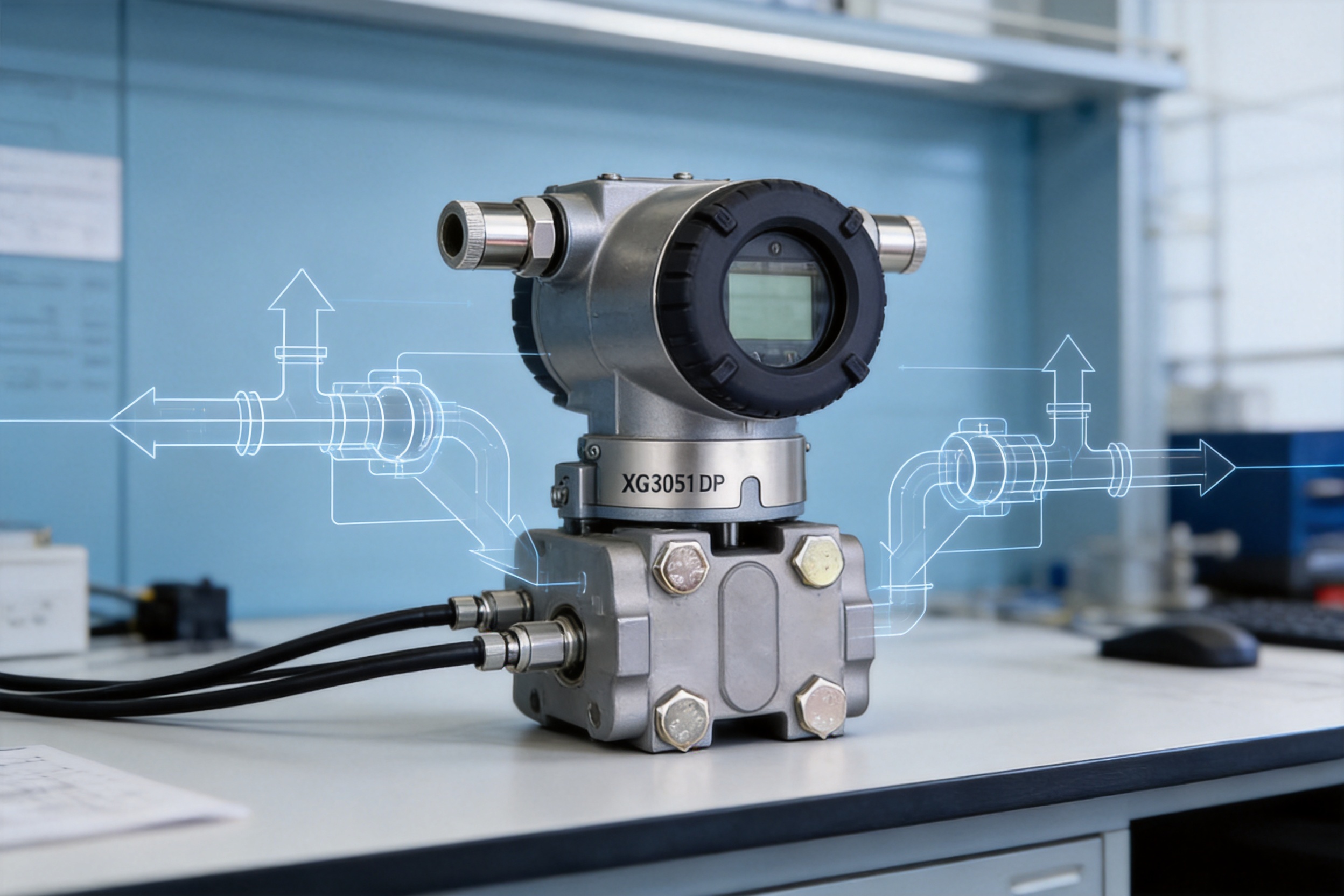
The XG3051DP model-selection structure allows the transmitter to be configured according to accuracy, range, diaphragm material, rated working pressure, process connection, seal material, housing, special functions, mounting, accessories, display, explosion-proof treatment, and additional options.
The available accuracy selections include versions with basic error of approximately ±0.05 percent, ±0.075 percent, and ±0.1 percent. HART-enabled 4–20 mA output is available, while a 4–20 mA analog-only version can be selected for systems that do not require digital communication.
The highest accuracy should be selected when the measurement contributes directly to custody transfer, production balance, tight process control, or a demanding instrumentation error budget. For general monitoring, an economical accuracy level may be sufficient.
The range code must be selected according to the expected differential pressure, minimum measurable value, static pressure, and required turndown. Available selections include:
| Range Code | Approximate Span | Typical Use |
|---|---|---|
| A | 0.1–1 kPa | Very low differential pressure, furnace draft, ventilation, and low-pressure gas service |
| B | 0.2–6 kPa | Low-pressure flow and filter monitoring |
| C | 0.4–40 kPa | General process flow, tank level, and filter applications |
| D | 2.5–250 kPa | Medium-to-high differential pressure service |
| E | 20–2,000 kPa | High differential pressure and demanding process systems |
The listed values are range-code limits rather than a recommendation for every process. The actual configured range must be checked against the expected normal value, maximum value, static pressure, fluid density, temperature, and process upset conditions.
316L stainless steel with silicone oil is the general-purpose configuration. A fluorinated fill fluid may be selected for specific compatibility requirements. Hastelloy C is suitable for many corrosive media, while gold-plated 316L can provide improved protection in selected permeation or chemical environments. FEP-coated 316L and tantalum are additional choices for specialized service.
For oxygen service, an oil-free treatment option is available. The specified oil-free configuration includes oil-free fill fluid, FKM seals, and application limits such as less than 6 MPa and less than 60 °C. Oxygen service must always be evaluated against the complete installation, cleaning, handling, and safety requirements.
The standard process connection uses 1/4-inch NPT and M10 internal threads. Versions are available without a bleed valve or with the bleed valve mounted on the rear, upper, or lower side of the flange. A vertical mounting flange with bleed valve is also available.
Bleed-valve position should be selected according to accessibility, impulse-line routing, process orientation, and maintenance space. A convenient valve position can simplify venting, draining, calibration checks, and removal of trapped gas or liquid.
The housing can be aluminum with a protective coating or stainless steel. Cable entry options include 1/2-14 NPT and M20 × 1.5. Local indication can be provided through a backlit LCD or an OLED display. The display option may change the minimum or lower ambient-temperature limit and should therefore be checked against the installation environment.
Mounting options include no bracket, a carbon-steel flat bracket, a carbon-steel bent bracket, a stainless-steel flat bracket, or a stainless-steel bent bracket. Stainless-steel brackets are useful in corrosive outdoor environments, while coated carbon-steel brackets may provide a cost-effective choice for general industrial installations.
For hazardous areas, intrinsically safe NEPSI or flameproof NEPSI treatment can be selected. A flameproof cable-entry device or increased-safety cable-entry device may be specified as an additional option. The complete installation must comply with the applicable hazardous-area classification, barrier requirements, cable-gland requirements, grounding rules, and local regulations.
Explosion-proof treatment is not simply a housing option. The transmitter, cable gland, wiring method, power supply, barrier, grounding, conduit, and inspection procedures must be treated as one certified system. Installation should be performed by qualified personnel familiar with the relevant protection method.
Correct installation is essential to achieve the specified performance. Before installation, verify the process medium, pressure range, static pressure, temperature, connection size, material compatibility, hazardous-area requirements, power supply, loop resistance, and signal type.
The high-pressure and low-pressure connections must be connected to the correct process points. Reversing the connections will reverse the output response and may produce an apparently incorrect measurement. The impulse lines should be designed to minimize leakage, blockage, condensation, gas pockets, liquid accumulation, and unequal thermal effects.
For liquid service, impulse lines should generally be arranged to prevent gas from becoming trapped in the sensing lines. For gas service, the arrangement should minimize liquid accumulation. For steam service, condensate legs should be equalized and protected against temperature differences. The exact arrangement depends on the process, vessel geometry, ambient conditions, and applicable engineering standards.
The transmitter should be mounted on a stable support. Excessive vibration can affect both the instrument and the impulse connections. The housing should be positioned so that the display, terminal block, bleed valves, and covers remain accessible for commissioning and maintenance.
Changes in mounting position parallel to the diaphragm are designed to cause no significant zero drift. If the position changes by more than 90 degrees relative to the diaphragm surface, a zero offset of less than approximately 0.4 kPa may occur. This offset can be corrected through zero adjustment, provided that the process is isolated and the adjustment is performed safely.
Electrical wiring should use a suitable DC power supply and correctly sized conductors. The terminal block accommodates conductors of approximately 0.5 to 2.5 mm². Cable entries must be sealed to maintain the intended enclosure protection. In explosion-proof installations, only approved cable-entry components and wiring methods should be used.
Reliable grounding of the housing is important. Signal cables should be routed away from strong electromagnetic sources where possible. Shielding and grounding practices should follow the requirements of the control system and the site electrical design.
During commissioning, inspect the transmitter for mechanical damage, verify the nameplate information, confirm the model code, check the diaphragm and seal materials, and ensure that the process connections are correctly tightened. Confirm that the power supply and loop resistance are within the permitted limits before applying power.
If HART communication is used, ensure that the loop includes an appropriate communication resistance and that the configurator is connected according to the control-system design. Check the measurement unit, lower range value, upper range value, damping time, output mode, alarm current, and display settings.
After the process is introduced, compare the transmitter output with the expected process condition. A zero check should be carried out only when both pressure sides are correctly equalized or isolated according to the application. Never open a process connection or loosen a flange under pressure.
Common causes of inaccurate output or large zero drift include leaks, blocked impulse lines, fluid accumulation, incorrect range migration, sudden ambient-temperature changes, and diaphragm overpressure. The recommended troubleshooting sequence is to inspect the impulse piping first, verify the valve positions, confirm the range settings, check the process temperature, and then perform zero and range calibration with a compatible HART controller or calibrated pressure source.
Preventive maintenance should include inspection of impulse lines, manifold valves, process connections, cable entries, housing covers, mounting brackets, grounding connections, and display condition. In dirty or corrosive service, the inspection interval should be shorter than in clean utility applications.
Compared with a basic analog-only differential-pressure transmitter, the XG3051DP offers greater configuration flexibility through optional HART communication, adjustable damping, selectable alarm behavior, and linear or square-root output. These functions can reduce the need for external signal-processing equipment and make commissioning more efficient.
Compared with a transmitter limited to one diaphragm material, the XG3051DP provides several material options. This is valuable because chemical compatibility often determines service life. A standard stainless-steel diaphragm may be suitable for one process but unsuitable for a high-chloride, strongly acidic, strongly alkaline, or oxygen-related application. The availability of Hastelloy, tantalum, coated, and gold-plated alternatives improves application matching.
Compared with a device available only in one pressure class, the XG3051DP provides several rated working-pressure options. This allows the user to select appropriate static-pressure resistance without automatically choosing an unnecessarily heavy or expensive construction.
Compared with a transmitter platform designed only for indoor use, the IP67 enclosure, broad ambient-temperature capability, stainless-steel housing option, hazardous-area selections, and multiple mounting accessories improve suitability for outdoor and industrial locations.
These advantages should not be interpreted as eliminating the need for proper engineering. No transmitter can compensate for incorrectly sized impulse lines, incompatible materials, poor grounding, uncontrolled temperature, or unsuitable pressure ratings. The value of the XG3051DP is that its configuration range gives engineers more tools to create a correct installation.
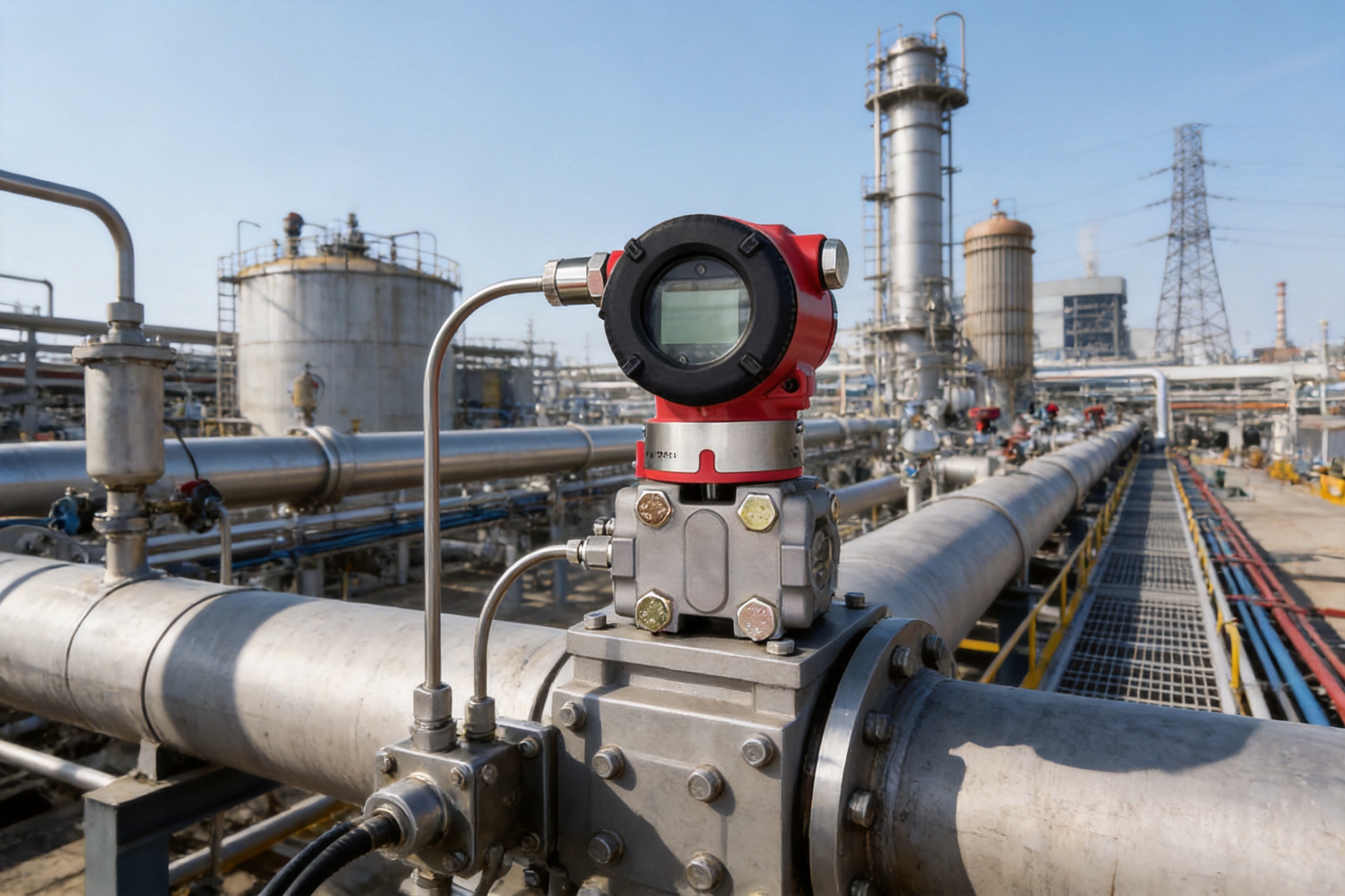
The XG3051DP directly measures differential pressure. Through differential-pressure conversion, it can also be used to measure pipeline flow, closed-container liquid level, pressure difference across filters, furnace negative pressure, and other process variables. It does not directly measure absolute pressure. For flow service, the HART square-root function or the specified square-root output configuration can be used to generate a flow-related signal.
The XG3051DP is a differential-pressure transmitter, not a dedicated absolute-pressure transmitter. It can measure the difference between a process pressure and a reference pressure when connected appropriately, but applications requiring direct absolute-pressure measurement should use a suitable absolute-pressure transmitter.
Possible causes include leaks, blocked impulse lines, liquid or gas accumulation, incorrect range-migration settings, rapid ambient-temperature changes, diaphragm overpressure, incorrect wiring, or an unsuitable material configuration. The first checks should normally focus on impulse-line condition, valve position, process connection tightness, power supply, and configured range. After these checks, recalibration may be required.
The transmitter uses a DC two-wire system. The signal and power share the same loop. The maximum circuit load must remain within the specified limit, and HART communication normally requires a suitable series resistance, commonly 250 Ω within the permitted communication-load range. Explosion-proof wiring must follow the applicable protection method, and the housing should be reliably grounded.
The correct selection depends on the exact chemical composition, concentration, temperature, pressure, and exposure time. 316L is suitable for many general services, but highly corrosive media or high chloride concentrations may require Hastelloy C, tantalum, FEP-coated stainless steel, or another specialized material. The seal material must also be checked because diaphragm compatibility alone is not sufficient.
A non-316L diaphragm may be necessary when the measured medium is strongly acidic, strongly alkaline, rich in chloride ions, chemically aggressive, or otherwise known to attack 316L. Special hygienic, pharmaceutical, or food-processing designs may also require a customized diaphragm and process connection. A material-compatibility review should be completed before ordering.
Many flow-measuring primary devices generate a differential pressure proportional to the square of flow. Square-root processing converts the measured differential pressure into a signal that is more proportional to flow. The square-root function is therefore useful for flow applications, but its accuracy should be evaluated separately because the stated square-root accuracy is approximately 1.5 times the linear reference accuracy.
Select a range code that covers the normal and maximum expected differential pressure while keeping the turndown ratio as low as practical. The static pressure and overpressure conditions must also be considered. Choosing a very broad range and then operating at a very small span can reduce the effective performance compared with selecting a more suitable range code.
Yes, intrinsically safe and flameproof NEPSI options are listed in the configuration system. The selected protection method must match the hazardous-area classification. Cable glands, barriers, power supplies, wiring, grounding, and installation practices must all comply with the relevant certification and local requirements.
Inspect the positive and negative impulse lines for leakage, blockage, trapped gas, accumulated liquid, or unequal temperature. Confirm that the range-migration settings are correct and that the diaphragm has not experienced overpressure. If the mechanical and process conditions are satisfactory, perform a zero check and recalibration with a suitable HART controller or calibrated pressure source.
The transmitter can be supplied without a display, with a backlit LCD, or with an OLED display. Display versions may have different lower-temperature limits, so the selected display should be matched to the ambient conditions.
The housing protection class is IP67 when the covers, cable entries, gaskets, and installation practices are correctly maintained. The protection rating does not remove the need for proper cable sealing, cover tightening, drainage considerations, and periodic inspection.
Before ordering an XG3051DP, the user should confirm the following information:
1. The process variable: differential pressure, flow, liquid level, filter pressure drop, furnace draft, or another application.
2. The minimum, normal, maximum, and possible upset differential pressure.
3. The maximum static pressure and required rated working pressure.
4. Process temperature, ambient temperature, vibration, humidity, and installation location.
5. Chemical composition and compatibility of the measured medium with the diaphragm, fill fluid, flange, and seals.
6. Required accuracy, turndown ratio, output mode, damping time, and alarm behavior.
7. Whether HART communication, a local display, square-root output, lightning protection, or oil-free treatment is needed.
8. Process connection, bleed-valve position, mounting orientation, bracket type, and accessories.
9. Housing material and cable-entry thread.
10. Hazardous-area classification and required explosion-protection treatment.
11. Required factory test report, calibration documentation, and project-specific inspection records.
A complete selection review helps prevent common problems such as incorrect range, insufficient static-pressure rating, incompatible diaphragm material, unsuitable seal material, missing cable-entry equipment, or inadequate loop power.
The XG3051DP Differential Pressure Transmitter is a flexible industrial instrument for measuring differential pressure and related process variables. Its capacitive sensing principle, 4–20 mA output, optional HART communication, adjustable range, square-root capability, configurable damping, selectable alarm behavior, and broad material options make it suitable for a wide range of process applications.
Its value is further strengthened by multiple pressure ratings, IP67 housing protection, local display choices, hazardous-area configurations, mounting accessories, and specialized diaphragm and fill-fluid selections. These options allow engineers to configure the transmitter around the actual process rather than forcing the process into a fixed instrument design.
For reliable field performance, the transmitter must be selected and installed as part of a complete measurement system. Process chemistry, pressure, temperature, impulse-line layout, valve arrangement, electrical load, grounding, communication resistance, and hazardous-area requirements all affect the final result.
The manufacturer’s experience in instrumentation, alloy materials, cables, and related industrial products provides a broad technical foundation for producing and supporting the transmitter. Its ISO-certified management systems, research and development resources, modern production equipment, inspection procedures, and international-market orientation further support consistent product quality.
When correctly configured and maintained, the XG3051DP can provide dependable measurement for petrochemical production, power generation, water treatment, environmental protection, metallurgy, pulp and paper, and many other industrial processes.
1. XG3051DP Differential Pressure Transmitter Product Technical Data and Model-Selection Information.
2. Industrial Process Measurement Practices for Differential-Pressure Flow and Level Applications.
3. IEC-Based Principles for Industrial Instrumentation, Signal Transmission, and Electromagnetic Compatibility.
4. ISO 9001 Quality Management Systems: Requirements.
5. ISO 14001 Environmental Management Systems: Requirements with Guidance for Use.
6. General Engineering Guidelines for Pressure Transmitter Installation, Impulse Piping, Calibration, and Maintenance.
7. Technical Guidance for HART-Compatible Two-Wire Process Instrumentation.



 INQUIRY
 English
 عربى
 русский
 中文简体