Reliable gas flow measurement is essential wherever compressed air, natural gas, hydrogen, oxygen, nitrogen, process gas, flue gas, biogas, or mixed industrial gases must be monitored, controlled, or totalized. In many facilities, the measurement environment is challenging. Gas temperature and pressure can fluctuate, pipe diameters can be large, flow rates can vary from nearly zero to a high operating capacity, and the gas may contain dust, corrosive components, or changing concentrations. Traditional volumetric flowmeters often require separate temperature and pressure compensation, while mechanical instruments may experience wear, vibration, or maintenance problems.
The XG-RSL series thermal gas mass flowmeter is designed to address these challenges through thermal diffusion measurement technology. Instead of depending on moving mechanical components or requiring external compensation modules, it measures the relationship between heat transfer and gas movement. The resulting instrument can directly measure gas mass flow and provide instantaneous flow, totalized flow, temperature, alarm, analog, pulse, and serial communication functions in one integrated solution.
Its design combines stable platinum resistance temperature detector technology, balanced sensor packaging, temperature self-compensation, proprietary signal-processing algorithms, flexible installation options, broad pipe-size compatibility, and multiple output configurations. These characteristics make the meter suitable for applications ranging from compressed-air management and natural-gas measurement to boiler control, environmental monitoring, chemical processing, metallurgy, food production, pharmaceutical manufacturing, and wastewater treatment.
Gas is compressible, which makes its volume change significantly with temperature and pressure. A volumetric flow reading taken at one operating condition may not represent the actual quantity of gas moving through a process at another condition. For this reason, many conventional systems require pressure transmitters, temperature sensors, density calculations, and compensation software. Every additional component increases installation complexity and creates another potential source of drift or failure.
A thermal gas mass flowmeter approaches the problem differently. It detects the ability of flowing gas to remove heat from a heated sensor. Because heat transfer is related to the mass of gas passing the sensing element, the meter can calculate mass flow directly. The electronics can then convert the measured signal into standard-condition volume flow, mass flow, velocity, or a totalized value according to the selected configuration.
This direct measurement approach is particularly valuable in utility systems. For example, a factory may need to identify compressed-air leakage, compare gas consumption between production lines, or allocate fuel costs to individual departments. If the instrument requires frequent manual correction for pressure and temperature, the data may be inconsistent. A thermal mass meter reduces the need for external correction and creates a more practical basis for energy management.
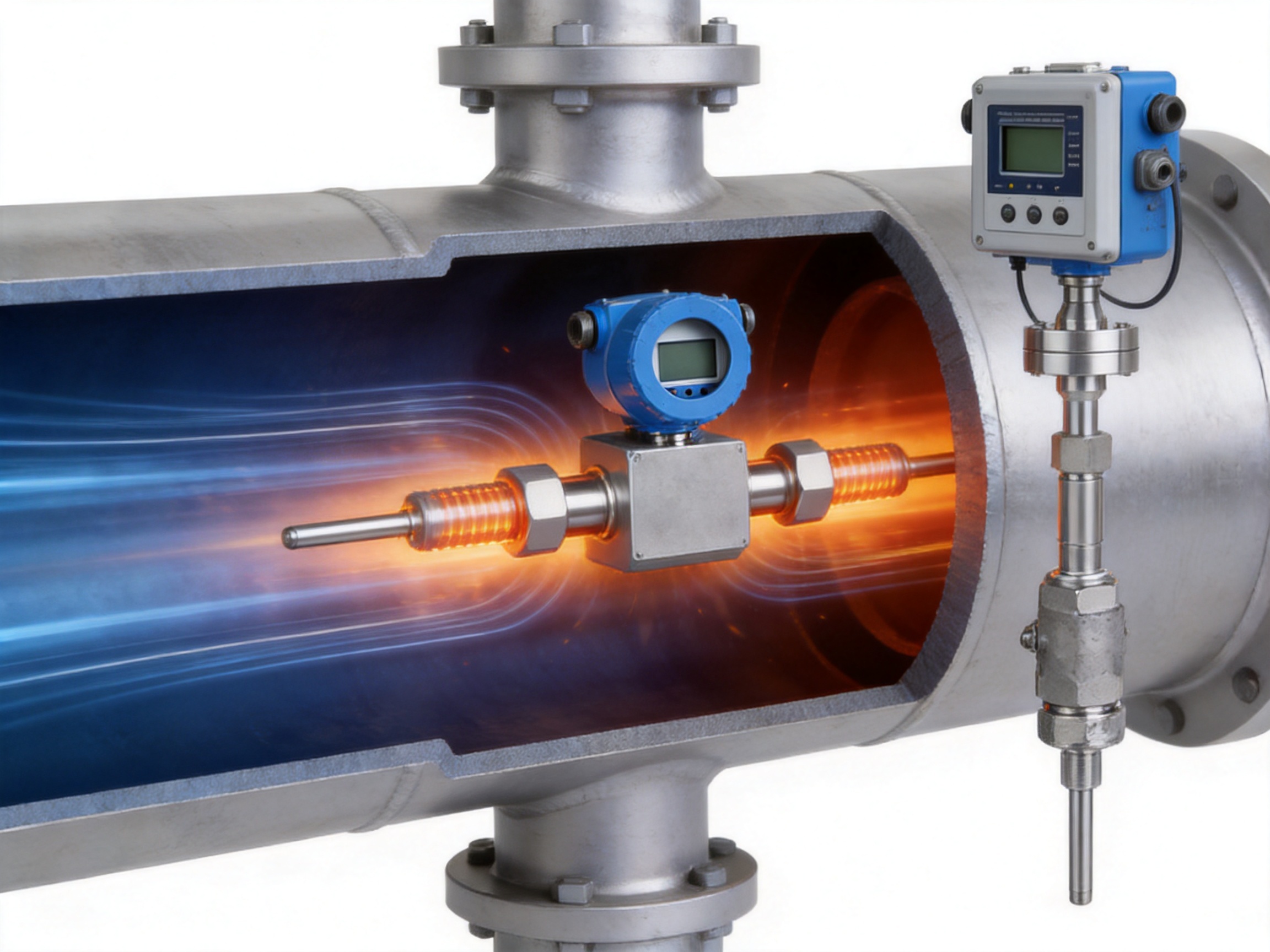
The XG-RSL series uses the principle of thermal diffusion. Its sensor incorporates two standard-grade platinum RTDs. One RTD operates as a controlled heat source, while the second RTD detects the surrounding gas temperature. When gas is stationary or moving slowly, the heated element loses a relatively small amount of energy. As gas velocity increases, more heat is carried away from the heated element.
The temperature difference between the two RTDs changes according to the heat removed by the flowing gas. This temperature difference has a nonlinear relationship with flow velocity and mass flow. The meter’s electronic system processes this relationship through calibrated algorithms and linearization functions, producing a usable flow signal for display, control, recording, or communication.
The balanced structure packaging of the sensor helps stabilize the thermal relationship between the sensing elements. It also supports self-compensation for changes in medium temperature. The purpose is not simply to make the sensor sensitive, but to keep its response predictable under changing process conditions. Stable construction, suitable material selection, and controlled calibration are therefore as important as the underlying thermal principle.
Unlike a turbine meter, the instrument has no rotating impeller. Unlike an orifice plate, it does not depend on a permanent pressure-reducing restriction. Unlike a basic volumetric meter, it can directly provide a mass-related measurement without relying on a separate pressure and temperature compensation assembly. These differences can reduce pressure loss, maintenance requirements, and installation complexity.
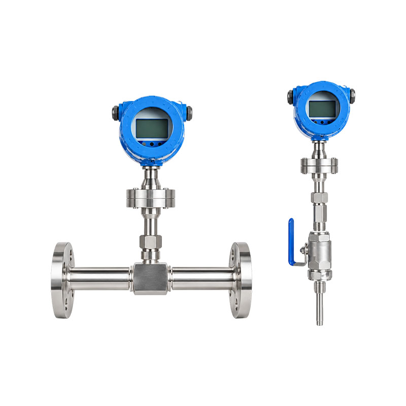
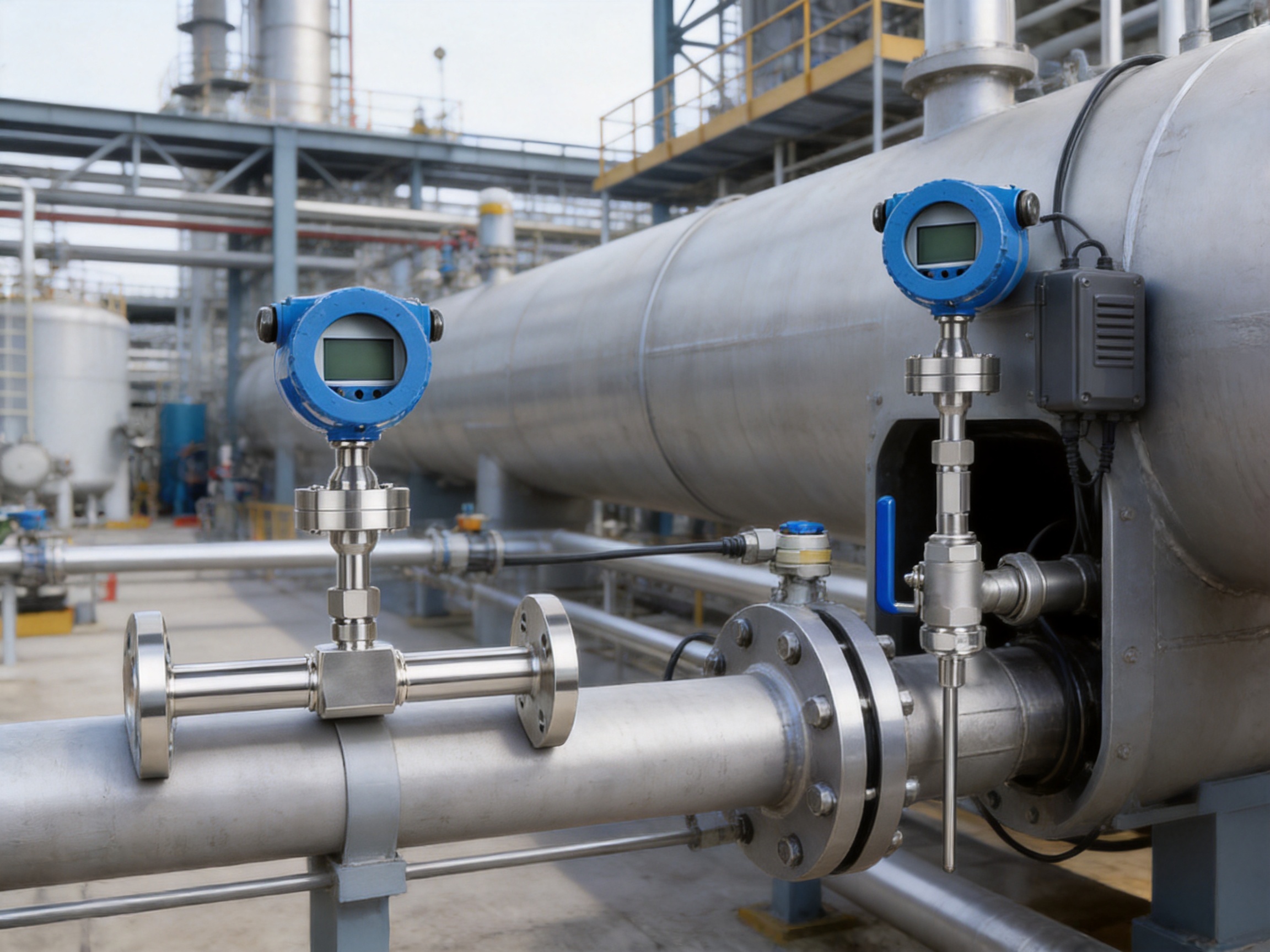
XG-RSL series thermal gas mass flowmeter
One of the most important advantages is the ability to measure gas mass flow directly through thermal diffusion. Under normal operating conditions, the instrument does not need separate temperature and pressure compensation modules to determine the standard-condition gas flow output. This is advantageous in systems where pressure fluctuates or where installing additional sensors would be difficult.
Direct measurement also simplifies the instrument architecture. A conventional compensation system may require a pressure transmitter, a temperature sensor, impulse lines, wiring, a controller, and software configuration. The XG-RSL solution integrates the sensing and processing functions into a single flowmeter platform. This can shorten installation time and reduce the number of components that must be calibrated and maintained.
The stated measuring range extends from 0 to 120 Nm/s under reference conditions of 20°C and 101.33 kPa. The broad range is supported by a high turndown capability. The typical turndown ratio is 100:1, while the design can support a larger 1000:1 range ratio according to user requirements and calibration conditions.
A broad range is useful when a pipeline experiences substantial changes between minimum demand and peak demand. A meter selected only for peak flow may provide poor resolution during low-demand periods. Conversely, a meter optimized for low flow may become overloaded during production peaks. Thermal sensing technology allows one instrument to cover a much wider operating window than many narrow-range instruments.
The instrument can be configured for applications where the gas velocity is very low. The minimum flow rate can approach zero, with a stated resolution as low as 0.001 m/s. This makes the meter suitable for leakage detection, low-demand utility lines, laboratory or pilot systems, ventilation monitoring, and process lines in which small changes are operationally important.
Low-flow sensitivity also supports energy-saving programs. In a compressed-air network, a facility may continue to consume a significant amount of air during nonproduction hours because of leaks, open valves, or inefficient equipment. A sensitive meter can help identify this base-load consumption and provide data for corrective action.
Because the thermal sensor does not require a large obstruction in the flow path, the instrument can operate with minimal additional pressure loss compared with many differential-pressure devices. Lower pressure loss is beneficial in compressed-air, natural-gas, and blower applications because the upstream equipment does not need to provide unnecessary additional pressure merely to overcome the measuring device.
Reduced restriction can contribute to lower operating energy and can make the meter appropriate for systems in which pressure availability is limited. It also avoids the permanent throttling effect associated with some primary elements. Actual pressure loss depends on the selected installation style, probe geometry, pipe size, gas properties, and process conditions, so final engineering verification remains important.
The XG-RSL series uses a fixed thermal sensor rather than gears, bearings, rotors, or impellers. The absence of moving parts reduces wear caused by long-term operation and makes the instrument less vulnerable to mechanical failure from vibration. It also helps minimize routine maintenance related to lubrication, bearing replacement, or mechanical obstruction.
This characteristic is especially valuable in remote installations, utility networks, high-cycle production facilities, and systems where shutdown access is limited. While the sensing element must still be protected from liquid accumulation, heavy deposits, and unsuitable process chemistry, its basic operation does not depend on mechanical movement.
The instrument can be used with pipe diameters from approximately 10 mm to 6000 mm. This range supports both compact process lines and large ducts or pipelines. Insertion installation is particularly practical for large pipes because it avoids the need to remove and replace a large section of piping with a full-bore inline meter.
For smaller lines, inline versions are available with flange or threaded connections. For larger systems, insertion versions can be selected with compression fittings, compression fittings combined with a ball valve, or flange connections. This gives engineers the ability to select a practical installation method based on pipe size, pressure, maintenance requirements, and available shutdown conditions.
The meter supports measurement of bidirectional medium flow. This is useful in systems where the direction of gas movement can change because of process switching, storage charging and discharging, parallel equipment operation, or ventilation reversal. Bidirectional capability can reduce the need for two separate meters or a complex directional piping arrangement.
Correct configuration of flow direction, zero point, totalization behavior, and output scaling is required during commissioning. The application engineer should confirm how reverse flow is represented in the display and control system, particularly when the totalized value is used for billing, production accounting, or energy reporting.
The sensing elements are based on stable platinum RTD technology. Platinum is widely used in industrial temperature sensing because of its repeatable resistance-temperature relationship and long-term stability. In a thermal flowmeter, sensor stability is critical because the measurement depends on a controlled and measurable temperature difference.
Standard sensor materials include 316 stainless steel, while Hastelloy and titanium can be selected for more demanding media. The standard protective probe sheath is 316 stainless steel, with Hastelloy available for applications requiring greater resistance to certain corrosive gases. Material selection should be based on the actual gas composition, concentration, moisture content, temperature, pressure, and possible contaminants.
The standard insertion probe diameter is approximately 19 mm, with smaller options such as 16 mm and 12 mm. Sensor diameters of approximately 3 mm and 2.5 mm are also available according to the configuration. A smaller probe can reduce the disturbance to the flow profile, while a stronger or larger protective structure may be appropriate for high-temperature or mechanically demanding environments.
Material compatibility should never be chosen solely from a general gas name. For example, the corrosive behavior of a gas can change considerably when moisture, oxygen, chlorine compounds, sulfur compounds, or process residues are present. The engineering review should therefore include the complete process composition and the possibility of condensation.
The XG-RSL series can be configured for medium temperatures ranging from −40°C to +100°C, −40°C to +200°C, −40°C to +450°C, or −40°C to +510°C. The high-temperature option expands the range of applications to furnace gas, hot air, boiler systems, heat-treatment equipment, cement production, and other processes where a standard low-temperature sensor would not be suitable.
High-temperature measurement requires more than simply selecting a high-temperature code. The installation must account for heat transfer through the probe, ambient temperature around the transmitter, insulation, vibration, thermal expansion, and the location of electronics. Where necessary, the transmitter should be positioned away from the hottest section or installed with a suitable connection arrangement.
The product information indicates that the instrument is not sensitive to small particles such as dust and can be applied to dusty or sand-laden gases. This gives it an advantage in selected industrial exhaust, combustion, mining, cement, and material-handling applications. However, “not sensitive to small particles” does not mean that unlimited solids can be allowed to accumulate on the sensor.
Heavy deposits may change the heat-transfer characteristics of the sensing elements and eventually affect accuracy. Large abrasive particles may also cause mechanical damage. The process review should consider particle size, concentration, velocity, abrasiveness, expected buildup, and whether periodic inspection or cleaning is required. A suitable filter, separator, purge system, or upstream process improvement may be recommended for severe conditions.
The meter can be configured for various corrosive gases with suitable material selection. The use of corrosion-resistant alloys, including Hastelloy or titanium options, can extend application flexibility. The complete wetted and exposed material arrangement should be reviewed because the sensor element, protective sheath, fittings, flange, gasket, and valve may not all have the same material.
In corrosive service, moisture control is particularly important. A dry gas may be compatible with a material while the same gas becomes highly corrosive after condensation. Drainage, heating, insulation, or a gas-conditioning system may be needed to prevent liquid formation around the probe.
For hazardous locations, the available protection configurations include intrinsically safe construction identified as ia II CT5 and flameproof construction identified as Ex d II CT4. The exact suitability depends on the hazardous-area classification, gas group, temperature class, installation method, cable glands, barriers, enclosure, and local regulations.
Explosion-proof selection must be confirmed before ordering. The complete installation—not only the flowmeter—must satisfy the requirements of the designated hazardous area. Wiring, grounding, isolation barriers, conduit systems, and inspection procedures should be handled by qualified personnel according to the applicable standards and site rules.
The product supports both insertion and inline installation. Inline meters can be supplied with flange or threaded connections and are normally selected for smaller or medium pipe sizes where a dedicated meter section is practical. Insertion meters are installed through a fitting, flange, or ball-valve connection and are often preferred for large pipes and ducts.
A compression fitting provides a relatively simple installation arrangement. A compression fitting with a ball valve allows the probe to be inserted or removed while the pipeline remains pressurized, provided that the pressure rating and operating procedure are suitable. A flange connection offers a robust arrangement for higher pressure, larger pipe sizes, or applications where a fixed insertion depth is preferred.
Although the product features can tolerate relatively short straight pipe sections in some descriptions, the recommended installation information specifies an upstream straight section of at least 10 pipe diameters and a downstream section of at least 5 pipe diameters. These recommendations should be followed whenever possible. Elbows, valves, reducers, tees, fans, dampers, and sudden changes in pipe size can create swirl, asymmetric velocity profiles, or turbulence that affects measurement stability.
The pipe should be installed so that liquid cannot collect around the sensor. Wet gas, condensation, or entrained droplets can change the heat-dissipation behavior and create a reading drift. The meter should not be installed at a point where condensate naturally accumulates unless appropriate separation and drainage measures are provided.
Strong vibration should also be avoided. Although the absence of moving parts makes the instrument mechanically robust, vibration can affect connections, signal wiring, mounting stability, and the flow profile. Support brackets may be required for large ducts, long probes, or installations near rotating machinery.
Insertion depth and orientation are important. The sensor should be positioned in the representative portion of the flow rather than close to the pipe wall, where velocity may be lower or deposits may accumulate. The direction mark or orientation guidance should be observed, and the probe should be secured against movement after adjustment.
| Item | Recommended Consideration |
|---|---|
| Upstream straight pipe | Preferably at least 10D, where D is the internal pipe diameter |
| Downstream straight pipe | Preferably at least 5D |
| Flow disturbances | Avoid immediate installation downstream of elbows, valves, reducers, tees, and fans |
| Liquid control | Prevent condensation, liquid droplets, and liquid accumulation around the sensor |
| Vibration | Use suitable support and avoid mounting directly beside severe vibration sources |
| Insertion depth | Position the sensor in a representative flow region and secure it firmly |
| Electrical grounding | Follow the wiring diagram and site grounding requirements |
| Hazardous areas | Confirm the protection type, barrier arrangement, cable entry, and local approvals |
The instrument is designed to convert the nonlinear thermal response into a linear flow signal. Its correction functions include 12-segment nonlinear correction that can be adjusted through the keypad and a built-in 10-segment nonlinear correction function. These functions help adapt the output to the calibrated flow range and improve the relationship between the measured signal and the displayed engineering value.
The product also supports 12-point dynamic correction for flow signals, with built-in 10-point correction. Dynamic correction can be useful when field conditions differ from the original calibration conditions or when a plant performs verification against a reference instrument. Any correction procedure should be controlled, documented, and performed using a traceable reference wherever the measurement is used for custody transfer, production accounting, or regulatory reporting.
Analog outputs include 4–20 mA DC for flow and, where configured, a separate 4–20 mA DC output for temperature. The maximum load is stated as 1000 ohms. The 4–20 mA standard is widely compatible with programmable logic controllers, distributed control systems, data acquisition modules, recorders, and industrial indicators.
Totalized pulse output is available for applications that need pulse-based accumulation or connection to a counter. Serial communication is supported through RS232 or RS485, and an RS485 MODBUS configuration is available. Digital communication can provide measured flow, totalized flow, temperature, diagnostic information, configuration parameters, and other available variables depending on the selected protocol and software arrangement.
The display option uses a large-screen LCD. It can show a seven-digit instantaneous flow value and an eight-digit totalized flow value. A clear local display allows operators to confirm operation without relying solely on the control room system. For installations without a display, the instrument can be selected with a broader ambient temperature range of −40°C to +85°C. The display version is specified for approximately −30°C to +70°C ambient temperature, with humidity below 90% RH.
Alarm functions are available through one or two relay outputs. The stated contact capability is up to 5 A at 220 V or 5 A at 30 VDC, with keypad-programmable settings. Alarms may be assigned to high flow, low flow, totalized quantity, temperature, or other configured conditions according to the instrument’s available functions and the control philosophy of the plant.
| Specification | Available Value or Configuration |
|---|---|
| Measurement principle | Thermal diffusion |
| Sensor technology | Two platinum RTDs, including a heated element and a temperature-sensing element |
| Measuring range | 0–120 Nm/s at 20°C and 101.33 kPa |
| Accuracy | ±1% of reading and ±0.5% of full scale |
| Typical turndown ratio | 100:1, with wider range ratios available according to calibration requirements |
| Pipe diameter range | Approximately 10 mm–6000 mm |
| Medium temperature | −40°C to +100°C; −40°C to +200°C; −40°C to +450°C; or −40°C to +510°C |
| Ambient temperature | −40°C to +85°C without display; −30°C to +70°C with display |
| Sensor materials | 316 stainless steel, Hastelloy, or titanium |
| Protective probe sheath | 316 stainless steel as standard; Hastelloy option |
| Flow direction | Bidirectional measurement |
| Flow output | 4–20 mA DC |
| Temperature output | 4–20 mA DC where configured |
| Communication | RS232, RS485, and RS485 MODBUS options |
| Power supply | 24 VDC / 600 mA; 220 VAC / 2 W; or 110 VAC / 3 W |
| Display | Seven-digit instantaneous flow and eight-digit totalized flow LCD |
| Process pressure | 1.6 MPa standard, with maximum configurations up to 20 MPa |
| Protection rating | IP65 |
| Installation | Insertion or inline |
Every flowmeter technology has an appropriate operating range, and selection should be based on the gas, pipe, pressure, temperature, accuracy requirement, and maintenance philosophy. The thermal gas mass flowmeter offers several practical advantages when compared with common alternatives.
Orifice plates, nozzles, and other differential-pressure devices are familiar and widely used. However, they create a permanent pressure drop and generally require pressure and temperature compensation for accurate gas mass or standard-volume measurement. Their accuracy can also depend on impulse-line condition, transmitter calibration, tap installation, and the quality of the upstream flow profile.
The thermal meter avoids a large primary restriction and can directly measure gas mass flow without separate compensation modules. This may reduce pressure loss, instrumentation count, and maintenance. Differential-pressure technology remains useful for high-pressure, high-temperature, or standardized applications, but thermal measurement can be more convenient for energy monitoring and large-pipe, low-pressure gas systems.
Turbine meters use a rotating element whose speed is related to flow velocity. They can offer good performance in clean, stable gas conditions, but bearings and moving parts may wear over time. They may also be more sensitive to lubrication, mechanical contamination, and changes in flow profile.
The XG-RSL series uses no moving parts and can measure low flow over a broad range. It is therefore attractive where long-term maintenance reduction and low-flow visibility are more important than the specific advantages of a turbine design.
Vortex meters detect vortices generated behind a bluff body. They are often used for steam, liquids, and gases, but their signal depends on a stable vortex pattern and an adequate flow velocity. Low-flow performance can be limited, and pressure loss is associated with the body installed in the pipeline.
A thermal meter can provide greater sensitivity near zero flow and may be more suitable for large gas ducts and compressed-air systems. Vortex meters may still be preferred for certain steam or multipurpose applications, especially where the process is clean and the required flow range is well defined.
Ultrasonic meters can measure gas without a substantial obstruction and can offer high performance when the gas, pipe, acoustic path, and installation conditions are suitable. However, they may require more complex electronics, longer straight runs, clean acoustic conditions, or higher budget allocation depending on the design.
The thermal meter provides a comparatively direct and practical solution for many industrial utility and process gases. Its broad range, insertion installation, analog outputs, and relatively simple sensor structure can make it easier to deploy across multiple pipe sizes.
Variable-area meters are simple, visible, and useful for local indication. Their output is usually local and their range is limited compared with an electronic thermal mass flowmeter. They may also require manual reading and may not be ideal for remote monitoring, totalization, or automated control.
The XG-RSL series provides electronic outputs, communication, alarms, totalization, and data integration. It is therefore better suited to modern plant-wide monitoring and process control.
The product is manufactured by a group with experience in temperature instruments, pressure instruments, flow meters, level instruments, alloy materials, cables, and related industrial products. This broad product scope is significant because a thermal flowmeter requires coordinated knowledge of sensing materials, electronics, mechanical fabrication, calibration, process connections, and industrial application engineering.
The company operates as a high-technology enterprise with a substantial production base, professional technical personnel, modern equipment, and formal inspection procedures. Its organization includes specialized business units covering instrumentation, alloy manufacturing, cable production, and precious-metal materials. This structure supports vertical technical coordination from material selection through sensor production, instrument assembly, testing, and final delivery.
Manufacturing quality begins with material control. Platinum RTD elements, stainless-steel parts, corrosion-resistant alloys, protective sheaths, fittings, circuit boards, displays, and enclosures must meet the specified requirements before they enter production. Correct material identification is particularly important for sensors exposed to high temperature, corrosive gases, pressure, and vibration.
Precision forming and machining are required to produce probes, compression fittings, flange connections, protective sheaths, and instrument housings. Dimensional accuracy affects insertion depth, sealing performance, mechanical strength, and alignment of the sensing elements. Surface condition also matters because rough or damaged surfaces can encourage deposits or create stress concentrations.
Sensor assembly requires careful control of the relationship between the heated RTD and the reference temperature RTD. The balanced packaging structure must maintain a stable physical arrangement and protect the sensing elements from mechanical damage. Electrical connections must be secure, insulated, and checked for continuity, resistance, and signal integrity.
Electronic assembly includes the signal-conditioning circuit, microprocessor or control electronics, analog output circuitry, communication interface, display, alarm relays, and power-supply components. These parts must be tested for stable operation under the specified voltage, temperature, load, and communication conditions. Proper sealing and enclosure assembly support the IP65 protection level when the instrument is correctly installed.
Calibration is central to thermal flowmeter production because the output depends on the thermal properties of the gas and the response of the sensor. The meter should be calibrated using the specified gas or a gas with known thermal behavior. Calibration data must be associated with the selected measuring range, pipe configuration, sensor construction, and output parameters.
Factory verification can include zero-flow checks, range-point checks, linearity evaluation, repeatability testing, output verification, display inspection, communication testing, alarm testing, and insulation or electrical safety checks. For applications involving mixed gases, the field configuration should be reviewed because a change in gas composition can alter thermal conductivity and therefore affect the measured result.
The company maintains ISO9001 quality management, ISO14001 environmental management, and occupational health and safety management certifications identified in the supplied information. These systems support controlled procedures for purchasing, production, inspection, corrective action, environmental management, and workplace safety. Certification does not replace application engineering, but it provides a structured framework for consistent manufacturing and traceability.
Products are developed to comply with applicable IEC international standards as well as national and industrial specifications. The exact standard and approval requirements should be confirmed for each project, especially in hazardous areas, high-pressure services, export installations, and applications subject to regulatory measurement rules.
The meter can be used for energy exchange, gas recovery from filling wells, natural-gas measurement, filling-station gas monitoring, gas quality-related process supervision, leakage testing, and flare-gas monitoring. Its direct gas measurement and broad range are useful where demand varies substantially or where a pipeline cannot easily accommodate a large inline meter.
Power facilities use gas measurement in fuel distribution systems, boilers, auxiliary systems, gas stoves, hydrogen systems, and primary or secondary air systems. Reliable measurement helps maintain combustion balance, monitor fuel consumption, detect abnormal operating conditions, and improve the efficiency of air and gas distribution.
Chemical plants may need to monitor smoke circulation, sampling-system gas, induced-draft fan flow, ammonia, hydrogen, oxygen, nitrogen, and other process gases. Corrosion-resistant materials and high-temperature versions can be selected when the process requires them. Gas composition should be reviewed carefully because changes in thermal conductivity may require recalibration or updated medium parameters.
Applications include blast-furnace gas, coke-oven gas, natural gas, heating-furnace gas, hydrogen, oxygen, ammonia, and gas filling systems. High-temperature and corrosion-resistant configurations can support process monitoring in steel rolling and heat-treatment operations. The installation must account for dust, heat radiation, vibration, and possible deposits.
The meter can monitor gases in wastewater treatment, smoke flow, boiler secondary and tertiary air, and boiler gas supply. Measurement data can support combustion control, ventilation, emissions management, and energy allocation across production areas.
Food and pharmaceutical facilities use controlled gas and air flows during processing, ventilation, sterilization, thermal oxidation, boiler operation, and carbon-dioxide treatment. The instrument’s electronic outputs and totalization functions can be integrated into process records and plant monitoring systems. Hygienic or clean-process requirements should be reviewed separately for each installation.
Environmental applications include biogas utilization, chlorine-gas treatment, aeration-tank gas monitoring, and chimney exhaust supervision. The gas may be humid, corrosive, or compositionally variable. Upstream separation, drying, material selection, and periodic verification are important in these services.
Compressed-air measurement is one of the most practical applications. The meter can help identify leaks, compare departments, establish production-specific consumption, and monitor nonproduction base load. Other applications include powder-to-gas ratio control in coal combustion, hot-gas control from vertical grinding machines, cement-process monitoring, and general factory gas distribution.
The instrument is intended for dry gas-phase measurement. It should not be used to measure steam or liquid. Large quantities of condensed droplets can adhere to the sensor, modify the heat-transfer characteristics, cause reading drift, and potentially damage the probe. In wet-gas service, a gas-liquid separator, demister, drain, heater, or drying system may be required before the flowmeter.
Gas composition changes can affect accuracy. The meter is calibrated according to the thermal conductivity characteristics of the selected calibration gas, such as air or nitrogen. If the process changes from one gas to another, or if the concentration of a mixed gas changes significantly, the thermal response may change. Applications with frequently changing composition should be evaluated for medium-parameter adjustment or recalibration.
Flow disturbances can also reduce accuracy. The recommended straight pipe sections should be provided wherever possible. If the available piping does not permit the recommended distance, a flow conditioner, alternate mounting point, or application-specific calibration may be considered. The final solution should be based on actual piping geometry rather than a general assumption.
Pressure and temperature limits must be respected. The standard process pressure is stated as 1.6 MPa, with maximum configurations up to 20 MPa. The selected connection, probe, valve, flange, gasket, and transmitter must all be rated for the operating pressure and temperature. The most restrictive component determines the safe operating limit.
The stated accuracy of ±1% of reading and ±0.5% of full scale should be interpreted together with gas composition, calibration conditions, installation quality, flow profile, temperature, pressure, and maintenance condition. The practical accuracy of a field installation depends on the complete measurement system.
The XG-RSL ordering structure allows the instrument to be configured according to nominal diameter, mounting type, temperature range, nominal pressure, process condition, signal output, and power supply. A typical selection begins with the XG-RSL series designation, followed by the nominal diameter or pipe size, installation form, temperature class, pressure class, process condition, output, and power code.
| Selection Category | Available Options | Typical Selection Consideration |
|---|---|---|
| Nominal diameter | Specified by pipe size, such as DN100 | Match the actual internal pipe diameter and installation arrangement |
| Mounting type | In-line or insertion | Use inline for suitable smaller lines; use insertion for large pipes or ducts |
| Insertion connection | Thread, flange, or flange with ball valve | Select according to pressure, maintenance, and online removal requirements |
| Temperature range | Up to +100°C, +200°C, +450°C, or +510°C | Choose above the maximum continuous process temperature with suitable margin |
| Nominal pressure | 0–0.6 MPa through 0–16 MPa options | Confirm operating and design pressure, including transients |
| Process condition | Standard, corrosion-resistant, explosion-proof, or high-temperature | Base selection on gas composition, area classification, and temperature |
| Signal output | No output, 4–20 mA, or RS485 MODBUS | Match the plant control and data-acquisition system |
| Power supply | 220 VAC or 24 VDC | Use the supply available at the installation location |
Before a final selection is made, the user should provide the gas name and composition, normal and maximum flow, minimum flow, operating pressure, operating temperature, pipe material and size, installation orientation, expected humidity, dust concentration, corrosive components, hazardous-area classification, required output, and preferred connection. These details allow the meter to be configured rather than merely selected from a nominal pipe diameter.
During commissioning, confirm that the flow direction, sensor orientation, insertion depth, connection tightness, power supply, grounding, output range, communication parameters, and alarm settings are correct. The pipe should be free from unexpected liquid accumulation, and the instrument should be allowed to stabilize before comparing it with a reference reading.
The zero-flow condition should be checked when the pipe is confirmed to be stationary. If the pipe cannot be isolated, the measured zero may be affected by bypass flow, natural convection, vibration, or pressure equalization. Zero adjustment should be performed only under a verified no-flow condition.
Routine maintenance is generally limited because the instrument has no moving parts. Nevertheless, inspection should include the probe condition, cable glands, enclosure seal, display, wiring, mounting hardware, process connection, and evidence of liquid or solid buildup. In corrosive or dusty services, inspection intervals should be determined by the process severity.
If the reading begins to drift, the first checks should include gas composition, condensation, sensor deposits, flow-direction changes, installation disturbance, pressure or temperature outside the configured range, and changes in the upstream piping. Cleaning should be performed carefully and according to the sensor-material requirements. Abrasive tools or aggressive chemicals may damage the sensing elements.
Periodic verification against a suitable reference meter can confirm continued performance. The frequency depends on the importance of the measurement, gas cleanliness, process stability, regulatory requirements, and historical drift. Calibration records should identify the instrument, gas or reference standard, test points, environmental conditions, and any correction applied.
Normally, no separate compensation modules are required for direct gas mass-flow measurement. The instrument uses thermal diffusion and can directly calculate the gas flow signal. It can also output standard-condition volume flow according to its configuration. Correct installation and appropriate calibration remain necessary because gas composition and sensor condition influence the thermal response.
No. The product is intended for the dry gas phase and is not suitable for steam or liquid measurement. Condensed water or other liquid droplets can adhere to the sensor, change heat transfer, cause measurement drift, and possibly damage the probe. Wet gas should be treated with suitable separation or drying equipment before measurement.
Humid gas may be measured when it remains in the gas phase and does not produce significant condensation on the sensor. If humidity is high enough to create droplets or liquid accumulation, the application becomes unsuitable without gas conditioning. The installation should be evaluated for dew point, cooling, drainage, and separator requirements.
Yes. Thermal conductivity and other thermal properties vary among gases. The meter is calibrated using specified gas characteristics, so a change in composition can produce a measurement error. Mixed-gas applications with stable composition can generally be configured appropriately, while frequently changing compositions may require parameter adjustment, recalibration, or another measurement technology.
The general recommendation is at least 10D upstream and 5D downstream, where D is the internal pipe diameter. Elbows, valves, reducers, tees, fans, and dampers should be located outside these sections whenever possible. If the piping cannot provide the recommended length, the application should be reviewed for flow conditioning or alternative installation.
Yes. The design supports low-flow measurement with a resolution stated as low as 0.001 m/s, and the minimum flow can approach zero. Actual performance depends on the selected range, gas properties, calibration, installation, and environmental conditions.
Yes. Bidirectional medium-flow measurement is supported. The control system should be configured correctly to handle reverse flow, display behavior, output polarity, and totalization requirements.
The stated pipe diameter range extends to approximately 6000 mm. Large pipes and ducts are generally handled with insertion-type installation. The probe position and flow profile should be evaluated carefully because large ducts may have substantial velocity variation across the cross-section.
No. The instrument can be supplied with or without a display according to the selected configuration. The large LCD version shows instantaneous and totalized flow. The no-display version has a wider stated ambient-temperature range and may be useful for remote or enclosed installations.
Available functions include 4–20 mA flow output, a temperature 4–20 mA output where configured, totalized pulse output, RS232 or RS485 serial communication, and RS485 MODBUS. One or two programmable relay outputs can also be available for alarms.
Explosion-protected configurations include intrinsically safe and flameproof versions. The exact product selection must match the site’s hazardous-area classification, gas group, temperature class, wiring method, and local certification requirements. Installation should be completed by qualified personnel.
Sensor materials include 316 stainless steel, Hastelloy, and titanium. The protective probe sheath is normally 316 stainless steel, with a Hastelloy option. Material selection must be checked against the complete gas composition, moisture level, temperature, pressure, and expected contaminants.
Maintenance generally includes checking the process connection, enclosure, cable entry, sensor condition, deposits, condensate, wiring, display, and output signals. Because there are no moving parts, mechanical wear is reduced. However, severe dust, corrosion, liquid, or changing gas composition can still require inspection and recalibration.
The XG-RSL series thermal gas mass flowmeter provides a practical solution for industrial gas measurement where wide range, low-flow sensitivity, low pressure loss, direct mass-flow measurement, and flexible installation are important. Its thermal diffusion principle eliminates moving parts and reduces dependence on separate temperature and pressure compensation equipment. Platinum RTD sensing, balanced structure packaging, linearization, dynamic correction, multiple outputs, bidirectional measurement, and high-temperature options further extend its usefulness.
The instrument is suitable for small process lines, large ducts, compressed-air systems, fuel-gas networks, boilers, furnaces, chemical plants, steel production, wastewater systems, environmental monitoring, and many other applications. Its performance is supported by configurable materials, insertion and inline connections, explosion-protection options, a broad temperature range, and communication functions for modern automation systems.
Its advantages are strongest when the application is engineered carefully. Dry gas service, correct material selection, suitable straight pipe sections, controlled condensation, appropriate calibration gas, proper insertion depth, and compliance with pressure and hazardous-area requirements are essential. When these factors are addressed, the meter can provide stable measurement, useful plant data, reduced maintenance, and improved control of energy and process-gas consumption.
The manufacturing organization behind the instrument adds further value through technical expertise in instrumentation, alloys, cables, electronics, sensor construction, quality systems, and industrial production. Controlled material procurement, modern manufacturing equipment, calibration procedures, inspection at multiple stages, and certified management systems provide a foundation for consistent product quality and long-term industrial service.
1. Product technical information for the XG-RSL series thermal gas mass flowmeter, including operating principle, features, specifications, installation forms, output options, and ordering structure.
2. Industrial thermal diffusion flow measurement principles and gas heat-transfer fundamentals.
3. General engineering practices for gas-flowmeter installation, straight pipe requirements, flow disturbance control, and condensation prevention.
4. Industrial instrumentation guidance for 4–20 mA transmission, RS485 communication, MODBUS integration, pulse totalization, and relay alarm applications.
5. Quality management, environmental management, and occupational health and safety system principles applicable to industrial instrument manufacturing.
6. General material-selection practices for stainless steel, Hastelloy, titanium, and platinum RTD components in industrial gas service.
7. Industrial hazardous-area engineering principles for intrinsically safe and flameproof instrumentation.




 INQUIRY
 English
 عربى
 русский
 中文简体