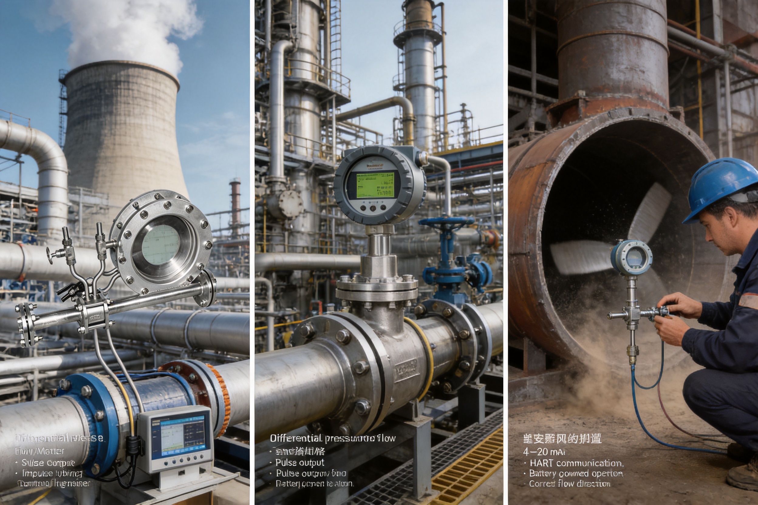
Accurate, stable, and economical flow measurement is essential to modern industrial production. Process plants depend on reliable flow data to control equipment, balance energy consumption, optimize material use, protect machinery, and support custody transfer. In power generation, petrochemical processing, metallurgy, municipal heating, and many other industries, the flow meter must operate under demanding conditions that may include high pressure, high temperature, changing density, long operating periods, corrosive fluids, and restricted installation space.
The XG-LG Series Flow Measurement Throttling Device is designed for these conditions. It is a differential pressure flow measurement system based on mature throttling technology, including orifice plates, nozzles, Venturi tubes, special-purpose orifice plates, and airfoil wind measuring devices. By combining standardized mechanical components with optional intelligent electronics, the series can support both traditional differential pressure measurement and integrated flow measurement with local display and multiple signal outputs.
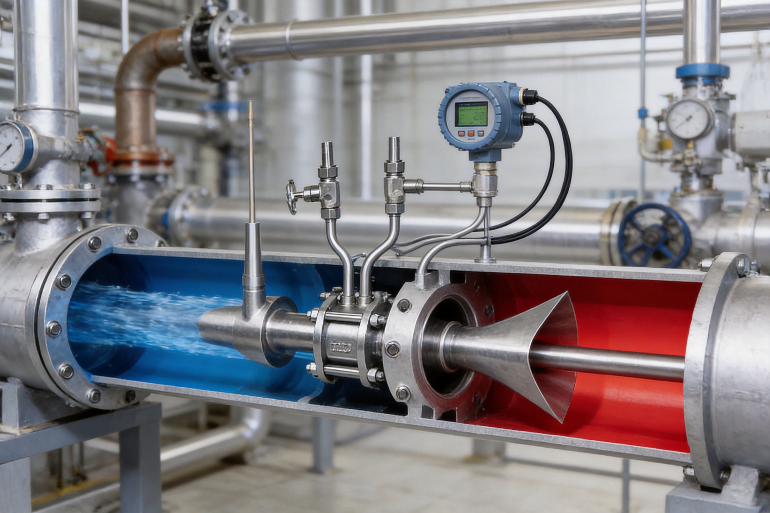
The fundamental principle is straightforward. When a fluid passes through a carefully designed restriction in the pipeline, its velocity increases and its static pressure decreases. The pressure difference between the upstream and downstream sides of the throttling element is related to the flow rate. A differential pressure transmitter or integrated flow unit converts this pressure difference into a flow indication or output signal.
Although the principle is simple, dependable performance requires careful design, accurate machining, suitable materials, correct pressure tapping, adequate straight pipe sections, and proper consideration of operating conditions. The XG-LG Series addresses these requirements through a broad configuration range, standardized design options, advanced manufacturing practices, and flexible integration with industrial control systems.
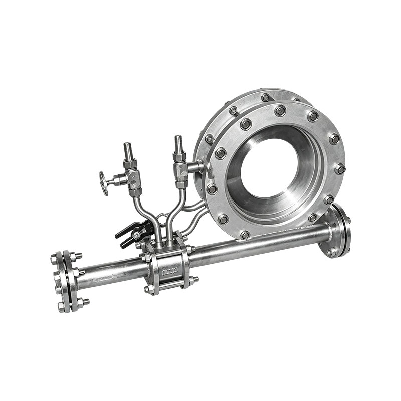
XG-LG Series Flow Measurement Throttling Device
The XG-LG Series is a configurable flow measurement throttling device for liquid, gas, and steam applications. It can be supplied as a split throttling element used with a separate differential pressure transmitter or as an integrated smart system with electronic processing, local flow display, and selectable signal outputs.
The series is suitable for standard and specialized flow measurement duties. Standard orifice plates provide a cost-effective solution for many clean-fluid applications. Nozzles are appropriate for higher-velocity and higher-temperature services, while Venturi tubes can reduce permanent pressure loss and provide a practical solution for larger pipe diameters. Eccentric, segment, annular, restriction, taper, double-orifice, and other configurations can be selected when process conditions require a customized flow profile.
For large air and gas ducts, the airfoil wind measuring device provides a specialized option. Its design is intended to offer stable measurement, high sensitivity, reduced pressure loss, and useful accuracy in large-diameter airflow applications. A reverse-blowing interface and dust-discharge arrangement can assist maintenance where dust accumulation is a concern.
The product family supports nominal diameters from small process lines to large industrial pipelines and ducts. Depending on the selected body type, the device can be manufactured for a broad range of beta ratios, pressure classes, materials, and installation arrangements. The upper pressure range of the throttling devices can reach approximately 42 MPa in accordance with the selected design, material, and process conditions.
A throttling device creates a controlled pressure loss in the pipeline. The flow rate is calculated from the measured differential pressure together with the internal pipe diameter, throat or bore diameter, fluid density, expansion behavior, and discharge characteristics of the selected device.
For incompressible liquids, the relationship between differential pressure and flow is generally governed by the square-root relationship. For gases and steam, pressure and temperature compensation may be required because density changes significantly with operating conditions. The integrated configuration can therefore be specified with pressure compensation, temperature compensation, or combined pressure and temperature compensation.
The reliability of this approach comes from the fact that the primary sensing element contains no rotating impeller, turbine wheel, bearing, or moving sensing mechanism. The throttling element is a precisely manufactured static component. Once properly installed and matched to the process, it can provide long-term measurement with limited mechanical maintenance.
The series is intended to support designs based on GB/T 2624 and ISO 5167 principles. Standardized orifice plates, nozzles, and Venturi tubes benefit from established calculation methods, published geometric requirements, and extensive experimental research. When the throttling component is correctly designed and processed according to the applicable standard, it may be used without the same type of complete real-flow calibration required by many nonstandard flow devices.
Standardization also improves project coordination. Process engineers can select a known primary element, instrumentation engineers can match it with a suitable differential pressure transmitter, and maintenance personnel can inspect the device using recognized dimensional and installation criteria. This reduces dependence on proprietary electronics and makes replacement or system expansion more manageable.
The XG-LG Series uses a structured model configuration system. The model identifies nominal diameter, structure type, measured medium, throttling body, pressure tapping method, material, static pressure range, mounting arrangement, process condition, compensation mode, signal output, and power supply. This allows the same product family to address a wide variety of process requirements without forcing every application into one fixed design.
| Configuration Item | Available Options | Typical Selection Consideration |
|---|---|---|
| Structure type | Integrated smart type or split type | Choose integrated electronics for local processing and outputs; choose split type for separate transmitter installation. |
| Measured medium | Liquid, gas, or steam | Selection depends on density, temperature, pressure, phase condition, and process cleanliness. |
| Primary element | Orifice plate, nozzle, Venturi, double Venturi, special orifice, restriction element, or airfoil device | Selection depends on pressure loss, pipe diameter, accuracy, contamination, and available straight length. |
| Pressure tapping | Corner ring chamber, corner drilled, flange, flange drilled, or radius tapping | Use the tapping arrangement required by the selected standard and piping configuration. |
| Material | Carbon steel, stainless steel, alloy steel, or nonmetallic material | Material is selected according to temperature, corrosion, pressure, and fluid compatibility. |
| Static pressure | Up to approximately 40 MPa in the standard selection code | The actual rating is determined by design, material, flange, temperature, and process requirements. |
| Mounting | Pipe-welded or flange-connected | Flanged construction supports convenient installation and removal; welded construction may suit permanent process lines. |
| Compensation | None, pressure, temperature, or pressure and temperature | Compensation is especially important for compressible fluids and changing operating conditions. |
| Output | None, 4–20 mA, pulse, or HART | Output is selected according to the plant control, monitoring, and communication system. |
| Power supply | Internal battery, battery plus selectable 24 VDC, or external 24 VDC | Power selection depends on installation access, energy consumption, and control system architecture. |
The standard orifice plate is one of the most widely used options. It is suitable for many liquid, gas, and steam applications and offers a favorable combination of simple structure, low purchase cost, easy replacement, and recognized calculation procedures. Standard orifice plates can cover pipe diameters of approximately 50 to 3,000 mm, with beta ratios commonly ranging from 0.20 to 0.75.
The standard nozzle is suitable for pipe diameters of approximately 50 to 500 mm and beta ratios of about 0.20 to 0.80. Nozzles are often selected for higher-velocity services or applications where a more robust inlet profile is preferred. Long-neck nozzles can cover approximately 50 to 630 mm pipe diameters, with beta ratios of approximately 0.20 to 0.80.
Venturi tubes are available in machined, rough-welded, and rough-cast forms. Machined Venturi tubes can generally cover diameters of approximately 50 to 250 mm, while rough-welded designs can extend to approximately 1,200 mm. Rough-cast Venturi tubes can cover approximately 100 to 800 mm. Venturi designs are commonly considered where permanent pressure loss must be controlled or where larger pipe sizes make an orifice plate less attractive.
Additional designs include Venturi nozzles, double Venturi devices, annular orifice plates, segment orifice plates, eccentric orifice plates, high-pressure lens orifice plates, double one-quarter-circle nozzles, double orifice plates, end orifice plates, taper orifice plates, wide-range orifice plates, restriction orifice plates, circular perforated plates, and airfoil wind measuring devices.
This broad selection is a major advantage over suppliers offering only one standard orifice format. Different process conditions produce different measurement challenges. A clean, stable liquid in a long straight pipeline does not require the same primary element as a dusty airflow, a high-pressure steam line, or a process stream containing suspended particles. The ability to select the geometry rather than force a universal design improves application suitability.
The beta ratio, commonly defined as the bore diameter divided by the internal pipe diameter, has a significant influence on differential pressure, rangeability, pressure loss, and measurement sensitivity. A smaller beta ratio generally produces a larger differential pressure for a given flow rate, while a larger beta ratio can reduce pressure loss but may reduce differential pressure at low flow.
The correct beta ratio must be selected using the minimum, normal, and maximum operating flow rates; process pressure; process temperature; fluid density; permissible pressure loss; transmitter range; and required accuracy. The broad beta ratio coverage of the XG-LG Series allows the device to be adapted to these competing requirements.
For special applications, the available ranges include approximately 0.10 to 0.80 depending on the primary element. Eccentric orifice plates and end orifice plates may be used within application-specific ranges of approximately 0.46 to 0.84. A conical inlet orifice may operate at a lower beta ratio, while circular perforated plates can offer a broader flow distribution for selected services.
Compared with turbine, paddlewheel, and mechanical variable-area meters, a throttling device has no rotor, shaft, bearing, or mechanical sensing assembly in the fluid stream. This eliminates wear associated with moving parts and reduces the risk of mechanical failure caused by bearing damage, excessive velocity, or solids impact.
The static construction is particularly valuable in high-temperature and high-pressure services. A properly selected material and geometry can operate in conditions that would challenge some mechanical flow meters. The absence of moving components also simplifies inspection and contributes to a long service life.
Standard orifice plates are relatively economical to manufacture and install. Their simple construction makes them attractive for large numbers of measurement points, utility systems, energy accounting, and process monitoring. The device can be paired with differential pressure transmitters from different manufacturers, which provides procurement flexibility and reduces dependence on a single proprietary electronics platform.
Lifecycle cost is also influenced by maintenance and replacement. A damaged or worn primary element can often be replaced without changing the entire measurement system. Standard flanged arrangements can make removal and inspection more convenient than replacing a complete inline electronic meter.
The series can measure liquids, gases, and steam when the primary element and calculation system are correctly selected. Unlike flow meters designed for only conductive liquids or only clean gases, differential pressure devices can be adapted to a broad range of single-phase fluids. Specialized geometries may also be considered for fluids containing limited amounts of impurities.
However, the phrase “broad compatibility” does not mean every throttling device is suitable for every fluid. Ordinary sharp-edged orifice plates may be unsuitable for high-solid-content slurry or highly abrasive media. In such cases, a wedge-shaped, V-cone, eccentric, or other specialized design may reduce blockage or improve maintainability. Engineering selection must always consider particle size, concentration, viscosity, corrosiveness, and erosion risk.
The split version can be installed with a separate differential pressure transmitter, allowing the user to select a preferred transmitter brand, communication protocol, enclosure, hazardous-area approval, and control system interface. This is useful for plants with existing instrumentation standards or centralized spare-parts programs.
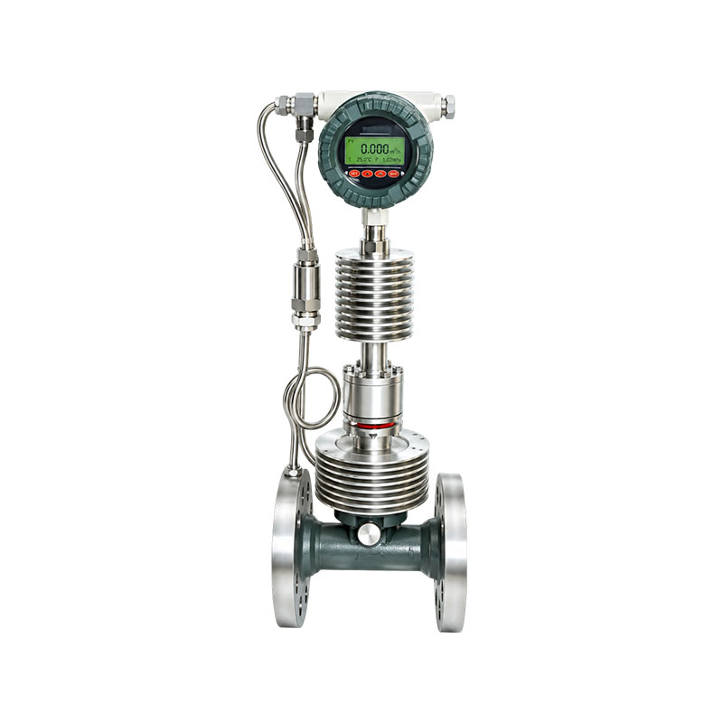
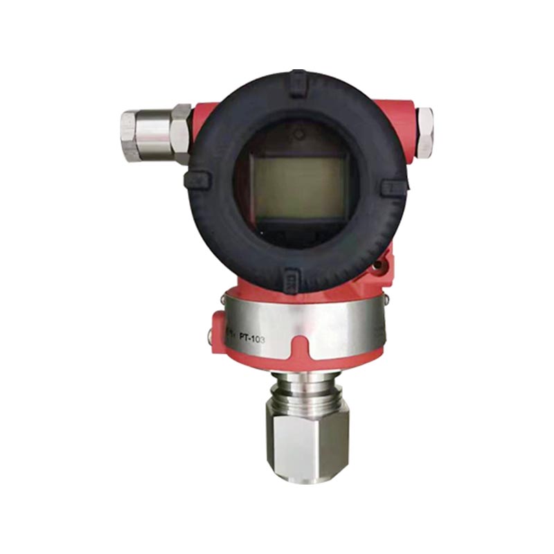
The integrated smart version combines the primary measurement function with advanced electronic processing. Depending on the specified configuration, it can provide local flow display and 4–20 mA, pulse, or HART communication. Pressure and temperature compensation may be incorporated when needed. This reduces the number of separate instruments and can simplify installation in locations where space is limited.
Standardized throttling components are widely recognized in industrial measurement practice. When designed, manufactured, installed, and maintained according to applicable standards, they can support measurement traceability, production management, energy accounting, and selected trade settlement applications.
For high-importance custody transfer or regulatory measurement, the complete installation still requires a suitable engineering review. The primary element, transmitter, pressure and temperature sensors, flow computer, impulse piping, calibration records, and operating conditions must be considered together. Standardization improves the technical foundation, but correct system implementation remains essential.
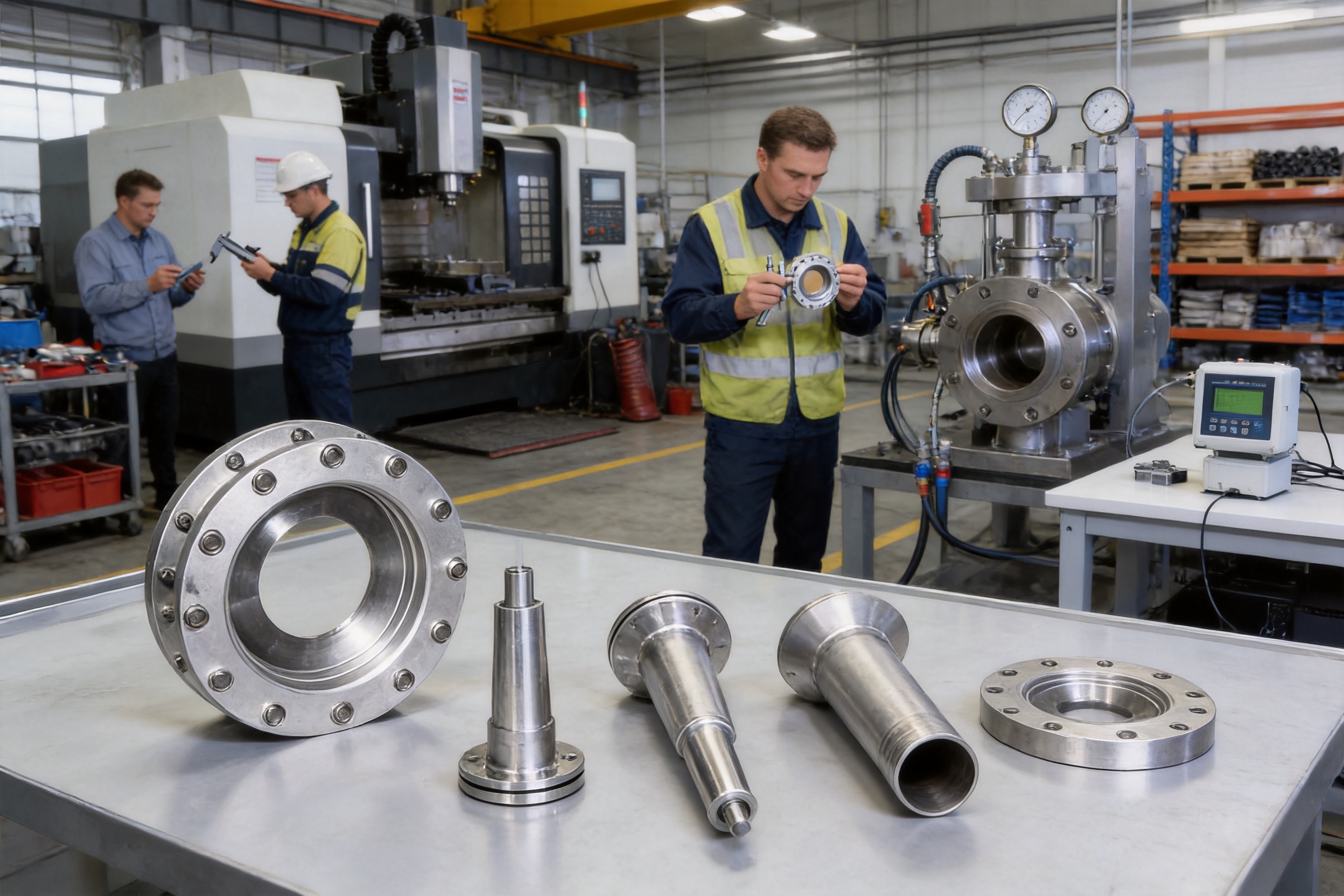
Product performance begins with manufacturing discipline. A throttling element may have a simple external appearance, but its measurement behavior depends on edge sharpness, bore geometry, surface finish, concentricity, plate flatness, nozzle profile, Venturi dimensions, pressure-tap location, and material stability. Small geometric deviations can influence the discharge coefficient, pressure recovery, permanent pressure loss, and measurement repeatability.
The manufacturing organization behind the series has operated in industrial instrumentation and related materials since 1997. Its broader technical structure includes temperature instruments, alloy materials, cables, precious metal products, pressure instruments, flow meters, and other industrial products. This combination of instrumentation and material expertise supports an integrated approach to product development.
More than 50 professional technicians and engineering personnel are involved in technical development, production support, process control, and inspection activities. Their work includes product design, material selection, drawing review, machining process development, assembly, testing, and application support.
For a flow throttling device, this multidisciplinary capability is important. The primary element must be designed together with its pressure connections, mounting structure, material grade, temperature limits, and instrumentation interface. Isolating these considerations can lead to an element that is geometrically correct but difficult to install, unsuitable for the process fluid, or poorly matched to the transmitter.
The series can be manufactured using carbon steel, stainless steel, alloy steel, or selected nonmetallic materials. Material selection is based on process pressure, operating temperature, corrosion behavior, fluid composition, mechanical strength, and compatibility with connected piping.
Carbon steel can provide an economical choice for suitable noncorrosive services. Stainless steel is commonly considered for improved corrosion resistance and hygienic or chemical applications. Alloy steel can be selected for demanding pressure and temperature conditions. Nonmetallic materials may be appropriate for certain corrosive or specialized applications when their mechanical and temperature properties satisfy the design requirements.
Material traceability is a key aspect of professional manufacturing. Material certificates, heat numbers, incoming inspection, dimensional verification, and controlled production records help ensure that the selected material is consistent with the approved design. For high-pressure applications, material identity and mechanical performance are especially important.
Advanced machining and processing methods are used to improve the consistency of critical flow passages and pressure-tapping features. The machining process may include cutting, turning, milling, boring, drilling, surface finishing, welding, heat treatment, and final dimensional correction according to the selected primary element.
For orifice plates, attention is given to bore diameter, bore roundness, plate thickness, edge condition, concentricity, and upstream surface quality. For nozzles, the inlet contour and throat dimensions require controlled machining. For Venturi tubes, the converging section, throat, diffuser, and internal transitions influence both measurement performance and pressure recovery.
Welded and cast Venturi designs require additional control because manufacturing tolerances and internal surface conditions can differ from those of machined products. Welding procedures, deformation control, internal inspection, and finishing are important to achieve a consistent flow path. Casting quality and dimensional correction are similarly important for rough-cast configurations.
Inspection procedures are applied at different stages of production. Incoming materials may be checked for specification, dimensions, surface condition, and identification. During processing, critical dimensions and geometric features are verified against approved drawings. Final inspection can include dimensional measurement, pressure testing, surface inspection, connection verification, marking, and documentation review.
For integrated smart units, inspection extends beyond the mechanical element. Electronic circuits, power supply behavior, signal output, display operation, communication functions, compensation settings, and enclosure integrity must be checked. Low-power circuit design is intended to reduce energy consumption and support stable operation, particularly where battery power is used.
Pressure testing and leakage checks are especially important for high-pressure throttling devices. The actual test method and acceptance criteria depend on the design pressure, material, connection type, applicable standard, and customer specification. The purpose is to verify structural integrity and sealing performance before shipment.
The company maintains ISO 9001 Quality Management System certification, ISO 14001 Environmental Management System certification, and GB/T 28001 Occupational Health and Safety Management System certification. These systems provide a structured framework for document control, process management, quality objectives, corrective actions, environmental responsibilities, and workplace safety.
Quality certification alone does not replace product engineering, but it supports consistent organization-wide procedures. Controlled drawings, purchasing requirements, inspection plans, production records, nonconformance handling, and customer feedback processes are essential for repeatable manufacturing. They also help maintain consistency when products are supplied for different industries and export markets.
The manufacturing group operates on a site covering more than 150 mu, with a construction area of approximately 60,000 square meters and nearly 300 employees. The facilities support production, machining, assembly, inspection, research, storage, and administrative activities.
A modern facility is valuable for flow measurement products because the production process may involve multiple stages and specialized equipment. Separate areas for raw material management, precision machining, welding, assembly, calibration, and final inspection can reduce cross-contamination, improve workflow, and support better process control.
Power plants use flow measurement throughout the steam-water cycle, combustion system, cooling system, compressed-air network, and fuel or gas supply system. The XG-LG Series can be considered for boiler steam, primary air, secondary air, circulating water, natural gas, and auxiliary utility lines.
Steam measurement often requires careful attention to pressure, temperature, condensate management, impulse piping, and material selection. Gas and air measurement may require compensation for density variation and consideration of dust or moisture. Cooling-water measurement may prioritize corrosion resistance, low maintenance, and economical installation across multiple lines.
Reliable flow data helps operators monitor boiler efficiency, balance combustion air, assess energy consumption, identify abnormal conditions, and support plant-level performance analysis. The absence of moving parts can be a practical advantage in locations where access is difficult or where vibration and temperature would affect mechanical meters.
Petrochemical plants contain extensive networks of process liquids, gases, steam, utility water, and feedstock. Flow measurement is used for material balance, process control, blending, refining, heating, cooling, and product transfer.
Different primary elements can be selected for different services. Stainless steel or alloy materials may be appropriate for corrosive or high-temperature streams. High-pressure lens orifice plates may be considered for demanding pressure conditions. Eccentric or segment designs can be evaluated where solids, gas pockets, or drainage behavior create challenges for a conventional concentric bore.
In process systems with limited installation space, V-cone or balanced throttling arrangements may be considered because they can require shorter straight pipe sections than some conventional orifice installations. The final selection must still be based on actual piping geometry and applicable measurement requirements.
Metallurgical facilities measure blast furnace gas, converter flue gas, cooling water, compressed air, oxygen-related utilities, and other process streams. These environments may involve high temperature, vibration, dust, corrosive components, and large pipe diameters.
Airfoil wind measuring devices can be useful for large-caliber airflow measurement. Their stable measurement behavior, high sensitivity, pressure-loss characteristics, and maintenance features are valuable in large air or gas ducts. A reverse-blowing interface and dust-discharge arrangement can support cleaning and reduce the impact of accumulation over time.
For cooling-water systems, a suitable Venturi or orifice design can provide reliable flow data with relatively straightforward maintenance. For dusty gas, the primary element, impulse connection, and purge or cleaning approach must be selected as a complete system.
District heating systems require flow measurement for steam, hot water, and natural gas. Measurement points may be distributed across long networks and may need to support energy allocation, billing, balancing, and operational optimization.
The economical design of a throttling device is attractive where many measurement points are required. Flanged construction can simplify replacement or inspection, while integrated electronics can provide local display and signal communication. Pressure and temperature compensation are particularly important for steam and gas, where density changes with operating conditions.
Accurate flow information can help identify imbalances between supply and return networks, evaluate heat delivery, monitor customer consumption, and detect abnormal operating conditions. The measurement system should be designed with appropriate temperature sensors, pressure sensors, condensate arrangements, and flow calculation methods.
Correct installation is essential to the performance of any differential pressure flow meter. Even a well-manufactured primary element can produce inaccurate results if installed backward, if pressure taps are blocked, or if nearby fittings distort the velocity profile.
The arrow or marked flow direction must agree with the actual process flow. An orifice plate installed in the wrong direction can produce small or unstable readings and may cause incorrect pressure recovery behavior. The bore, bevel, gasket arrangement, and pressure-tap orientation must match the approved drawing.
For liquid services, the piping arrangement should prevent unwanted gas pockets at the pressure taps. For gas services, the arrangement should limit liquid accumulation. Steam installations generally require appropriate condensate formation and equalization in the impulse lines so that the transmitter receives a stable and representative pressure signal.
Upstream elbows, valves, reducers, expanders, pumps, tees, and other disturbances can produce swirl or an uneven velocity profile. Standard orifice plates have defined straight-pipe requirements intended to allow the flow to develop before reaching the primary element. The required length depends on the upstream disturbance, beta ratio, pipe roughness, and applicable standard.
When a site has limited straight length, a conventional orifice plate may not be the best choice. V-cone, balanced, or other specialized devices can sometimes reduce the required straight-pipe length. However, the actual installation should be reviewed using the manufacturer’s technical data and the applicable engineering standard rather than relying on a general assumption.
Impulse lines connect the high- and low-pressure taps to the differential pressure transmitter. They must be correctly routed, supported, sealed, and protected from freezing, condensation, blockage, vibration, and accidental damage. Leakage or fluid accumulation in the impulse piping is a common cause of inaccurate measurement.
For dirty or abrasive fluids, impulse lines may require flushing, purging, heat tracing, or special isolation arrangements. For high-temperature fluids, condensate pots, cooling sections, or suitable remote seals may be considered. The objective is to deliver a stable pressure signal to the transmitter without changing the relationship between process pressure and measured differential pressure.
Gaskets must not protrude into the flow passage. Incorrect gasket positioning can disturb the velocity profile, reduce the effective bore, create leakage, and introduce measurement error. Flanges should be aligned so that the throttling element is centered in the pipe. Bolts should be tightened according to an appropriate sequence and torque practice.
The design should be based on actual minimum, normal, and maximum pressure, temperature, flow, density, viscosity, and composition. Significant differences between design conditions and operating conditions can produce inaccurate readings or exceed the transmitter range.
For gases and steam, pressure and temperature changes directly affect density. A fixed-density calculation may be acceptable only within a narrow and stable operating range. Where conditions fluctuate, pressure and temperature compensation should be considered in the flow computer or integrated smart system.
Routine maintenance for a throttling device is generally simpler than for flow meters with moving internal parts, but it should not be neglected. Maintenance programs should be based on the medium, operating pressure, temperature, cleanliness, abrasiveness, and importance of the measurement point.
Small flow readings or unstable readings may result from reversed installation, worn bore edges, blocked pressure taps, leakage in impulse piping, trapped gas or liquid, insufficient straight pipe, incorrect transmitter range, or a mismatch between actual and design process conditions.
The first troubleshooting step should be a comparison of the indicated value with the actual process condition. Operators should then verify the flow direction, inspect the primary element orientation, check isolation valves, examine impulse piping, and confirm that the transmitter is properly zeroed and ranged.
For liquids, trapped gas in the impulse lines can reduce or distort the differential pressure. For gases, accumulated liquid can create a similar problem. Steam systems may experience condensate imbalance between the two impulse legs. A systematic inspection is more effective than immediately changing the transmitter.
Clean fluids normally produce limited wear, but abrasive particles, high-velocity solids, and corrosive components can gradually change the bore or flow profile. Wear changes the effective geometry and therefore the discharge behavior. Impurities may also accumulate around pressure taps or in the impulse lines.
For impurity-containing or abrasive services, inspection is recommended within approximately one to two years, depending on operating conditions. The actual interval should be shortened when the fluid contains significant solids or when measurement results are critical. If the bore or edge is no longer within acceptable limits, the throttling element should be repaired or replaced.
Routine activities include checking for external leakage, confirming flange and connection tightness, inspecting impulse tubing and valves, verifying display and output signals, and checking whether the indicated value is consistent with process expectations.
Annual inspection may include pressure-tap condition, impulse-piping cleanliness, valve operation, transmitter zero stability, and the integrity of insulation or heat tracing. Periodic removal and dimensional inspection of the primary element should be scheduled according to the fluid and service severity.
Maintenance records should include inspection date, operating conditions, observed wear, cleaning performed, dimensional results, transmitter status, and replacement parts. These records support predictive maintenance and provide useful evidence for measurement traceability.
The integrated smart configuration combines the mechanical throttling element with electronic measurement and calculation functions. It can provide local flow indication and selected output signals, including 4–20 mA, pulse, and HART communication.
The 4–20 mA output is widely used in industrial control systems because it is compatible with distributed control systems, programmable logic controllers, data acquisition systems, and monitoring instruments. Pulse output can support totalization or flow accumulation where the receiving system is designed for pulse input. HART communication can provide access to configuration, diagnostic, range, and process information over the analog signal loop.
Pressure and temperature compensation can improve measurement quality for gases and steam. A pressure-compensated system corrects density changes associated with line pressure, while temperature compensation addresses thermal changes. A combined pressure and temperature compensation mode provides a more complete correction when both variables vary materially.
Low-power circuit design helps reduce energy consumption and can support battery operation in remote or difficult-to-wire locations. The available power configurations include an internal battery supply, a battery plus selectable 24 VDC supply, and an external 24 VDC supply. This flexibility allows users to balance installation convenience, operating duration, communication requirements, and maintenance access.
The competitive value of the XG-LG Series is based on more than a single specification. It combines mature differential pressure technology, broad primary-element selection, flexible electronics, material options, standardized design, and manufacturing support from an established industrial instrumentation organization.
Some competing products may focus on advanced electronics but offer limited primary-element choices. Others may provide inexpensive orifice plates but lack integrated compensation, signal flexibility, or specialized designs for difficult applications. The XG-LG Series covers both ends of this requirement spectrum. It can be supplied as a simple and economical mechanical device or as an intelligent flow measurement system with digital functionality.
Its large selection of body types also helps reduce the need for separate suppliers. One project may require standard orifice plates for utility water, nozzles for high-temperature steam, Venturi tubes for large cooling-water lines, eccentric elements for process liquids, and airfoil devices for large air ducts. A broad product platform simplifies technical coordination and purchasing.
The ability to match the device with differential pressure transmitters from different brands is another practical advantage. Users can maintain existing instrumentation standards, select transmitters according to hazardous-area requirements, or integrate the primary element into a broader plant modernization program.
Manufacturing depth further strengthens the offering. The group’s capabilities in alloy materials, industrial cables, temperature instruments, pressure instruments, and flow products provide a wider technical base than a supplier focused only on one flow meter category. This is valuable when the project requires coordinated material selection, instrumentation matching, and process-specific engineering.
Finally, the product is supported by quality management systems, modern production facilities, technical personnel, inspection procedures, and experience serving domestic and international markets. These factors help customers reduce technical risk during selection, installation, commissioning, and long-term operation.
Accurate selection requires more than nominal pipe diameter. Customers should provide the inner and outer diameters of the pipe and the pipe material, together with the process information necessary for calculation and mechanical design.
Important data normally includes fluid name, phase condition, minimum flow, normal flow, maximum flow, operating pressure, design pressure, operating temperature, design temperature, density or molecular weight, viscosity, compressibility, solids content, corrosive components, allowable permanent pressure loss, pipe schedule, pipe material, flange standard, installation location, available straight pipe length, hazardous-area classification, and required output signals.
For steam and gases, pressure and temperature ranges are especially important. For liquids, viscosity, vapor pressure, entrained gas, and suspended solids should be considered. For dirty fluids, particle size and concentration help determine whether a standard orifice is appropriate or whether a specialized element should be evaluated.
The selection process should also identify whether the measurement is intended for process control, monitoring, energy management, inventory control, or trade settlement. The required accuracy, verification method, documentation, and calibration approach may differ according to the purpose of the measurement.
A throttling device creates a controlled pressure difference in a pipeline. The differential pressure is measured and converted into a flow rate using the geometry of the primary element and the physical properties of the fluid. The device can be used with a separate differential pressure transmitter or supplied as an integrated smart flow measurement unit.
No. A standard orifice plate is suitable for many clean, single-phase liquid, gas, and steam applications, but it may not be appropriate for high-solid-content slurry, strongly abrasive media, or fluids that are likely to block the pressure taps. A V-cone, wedge-shaped, eccentric, segment, or other specialized throttling device may be more suitable after reviewing the actual medium properties.
Possible causes include incorrect installation direction, blocked or leaking impulse lines, trapped gas in liquid-service impulse piping, accumulated liquid in gas-service impulse piping, insufficient straight pipe, incorrect transmitter range, worn throttling geometry, or operating pressure and temperature that differ substantially from the design conditions.
Yes. Straight pipe requirements depend on the primary element, beta ratio, upstream fittings, pipe condition, and applicable standard. Standard orifice plates generally require more careful upstream and downstream piping conditions than some specialized designs. Where space is limited, a V-cone or balanced device may be considered, subject to engineering verification.
The beta ratio describes the relationship between the bore or throat diameter and the internal pipe diameter. It affects differential pressure, pressure loss, sensitivity, flow range, and the calculation coefficient. The correct value must be selected from the actual operating range and allowable pressure loss rather than chosen only from the pipe size.
Yes. The series includes configurations for steam measurement. Steam applications require appropriate pressure and temperature data, suitable materials, correctly arranged impulse piping, and compensation when operating conditions vary. Condensate management and transmitter installation are important for stable measurement.
Yes. The airfoil wind measuring device is designed for large-caliber airflow applications. It is intended to provide stable measurement, high sensitivity, and controlled pressure-loss characteristics. The reverse-blowing interface and dust-discharge arrangement can assist maintenance in dusty environments.
Depending on the selected integrated configuration, available outputs include 4–20 mA, pulse, and HART communication. A split configuration can be paired with a separate differential pressure transmitter selected according to the plant’s control and communication requirements.
The integrated options include internal battery supply, battery plus selectable 24 VDC supply, and external 24 VDC supply. The appropriate choice depends on whether the installation is remote, whether continuous wired power is available, and which communication and display functions are required.
Routine checks should be performed according to the process risk and service conditions. Pressure taps and impulse lines are commonly checked at least annually. For impurity-containing or abrasive media, removal and inspection of the bore or throat within approximately one to two years is recommended, with a shorter interval if wear is severe or the measurement is critical.
Standard throttling components designed according to GB/T 2624 and ISO 5167 principles can support measurement traceability and energy accounting when the complete system is correctly designed and installed. For custody-transfer applications, the project should define accuracy, verification, calibration, documentation, compensation, and legal requirements before purchase.
At minimum, provide the pipe inner and outer diameters, pipe material, fluid type, flow range, pressure, temperature, density or molecular weight, viscosity, pipe connection information, available straight length, required material, installation method, output signal, power supply, and any corrosion, solids, hazardous-area, or high-temperature requirements.
The XG-LG Series Flow Measurement Throttling Device provides a practical and adaptable approach to industrial flow measurement. Its foundation is a proven differential pressure principle supported by standardized geometry, extensive application experience, and a wide range of primary-element designs.
The series offers the advantages of static construction, long service life, broad medium compatibility, economical installation, flexible transmitter matching, and suitability for high-pressure and high-temperature applications. Standard orifice plates address common process duties, while nozzles, Venturi tubes, special orifice designs, and airfoil devices provide solutions for more demanding conditions.
Its integrated smart configuration extends the value of the mechanical device by adding local display, selectable signal outputs, pressure and temperature compensation, HART communication, and flexible power supply options. Low-power circuit design can support remote installation and reduce energy consumption.
Manufacturing strength is equally important. Engineering personnel, material expertise, precision machining, inspection procedures, quality management systems, modern facilities, and experience across industrial instrumentation categories support consistent product development and production. These capabilities help ensure that the device is not only technically suitable on paper but also practical to manufacture, install, maintain, and integrate.
When the primary element is correctly selected, manufactured, installed, and maintained, the XG-LG Series can provide dependable measurement for power plants, petrochemical facilities, metallurgical operations, municipal heating networks, and general industrial processes. It offers a balance of mature technology, configuration flexibility, lifecycle economy, and intelligent integration for customers seeking a reliable alternative to more complex or mechanically sensitive flow meter technologies.
1. ISO 5167, Measurement of Fluid Flow by Means of Pressure Differential Devices Inserted in Circular Cross-Section Conduits Running Full.
2. GB/T 2624, Measurement of Fluid Flow by Means of Pressure Differential Devices Inserted in Circular Cross-Section Conduits Running Full.
3. International Society of Automation, Industrial Process Measurement and Control Engineering Practices.
4. American Society of Mechanical Engineers, Fluid Meters: Their Theory and Application.
5. International Electrotechnical Commission, Industrial-Process Measurement and Control Standards.
6. Manufacturer technical information for the XG-LG Series Flow Measurement Throttling Device.
7. General engineering practices for differential pressure transmitter installation, impulse piping, pressure tapping, and flow measurement maintenance.



 INQUIRY
 English
 عربى
 русский
 中文简体