Accurate liquid-level measurement is essential wherever storage tanks, process vessels, dosing systems, and wastewater equipment contain corrosive liquids. Acids, alkalis, salts, plating solutions, chemical reagents, and aggressive wastewater can rapidly damage ordinary carbon-steel instruments, exposed electrical sensors, and poorly protected mechanical indicators. A suitable level instrument must therefore do more than show the height of a liquid. It must resist chemical attack, prevent leakage, operate reliably over long periods, and provide information both at the installation site and in a central control room.
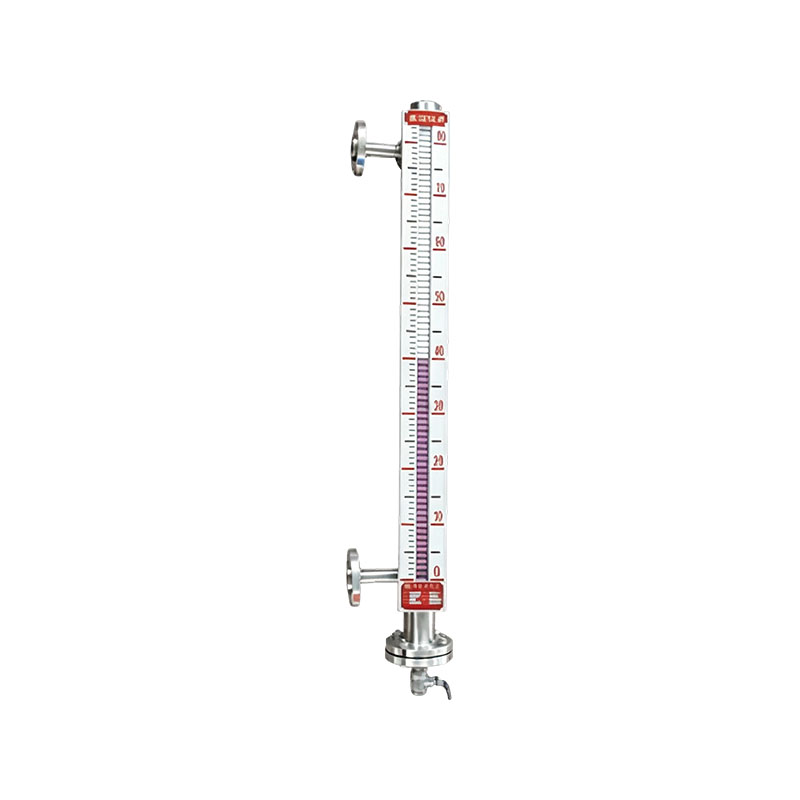
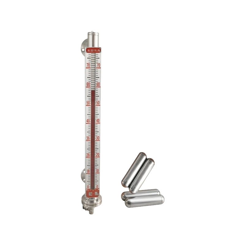
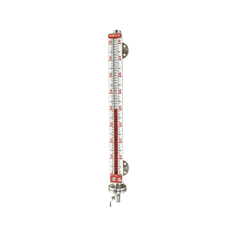
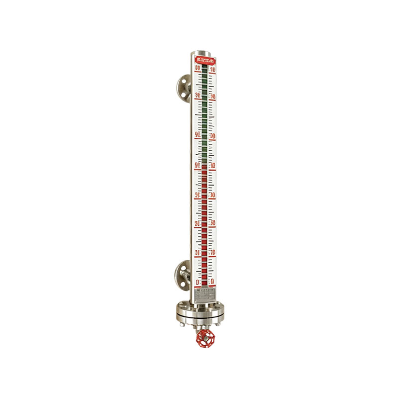
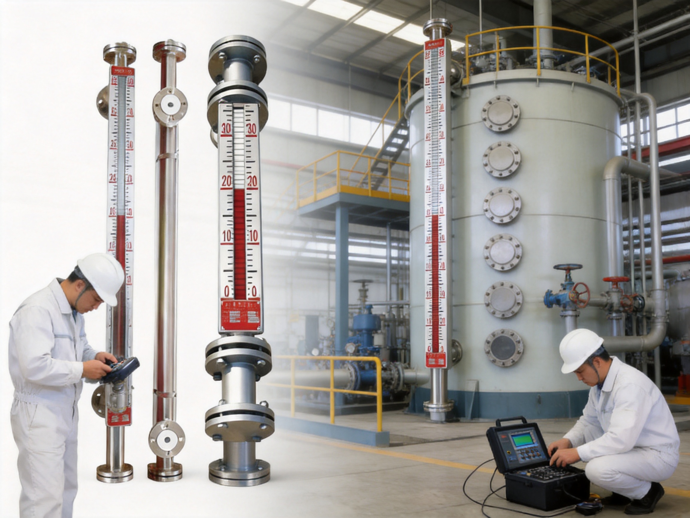
The UZC-A03F anti-corrosion magnetic level gauge is designed for these demanding measurement duties. It combines a corrosion-resistant chamber, a magnetic float, an external visual indication system, and optional remote transmission and alarm functions. Depending on the process requirements, the liquid-contacting chamber can be manufactured from PP or PVC, or from stainless steel lined with PP, PTFE, or other protective materials. This construction allows the instrument to be adapted to a broad range of corrosive storage and process applications.
The instrument is especially suitable for acidic and alkaline solutions that operate at relatively low or moderate temperature and pressure. It can be used on chemical storage tanks, wastewater treatment equipment, electroplating systems, pharmaceutical process vessels, metallurgical pickling lines, and similar installations. With an optional XG/UQZ-08 two-wire transmitter, the gauge can provide a 4–20 mA signal for remote level monitoring. Upper- and lower-limit level switches can also be fitted for alarm and control functions.
In comparison with conventional sight glasses, direct-contact electrical probes, and unprotected metal level indicators, the anti-corrosion magnetic level gauge offers a more integrated approach. It provides local visibility without requiring operators to open the tank or approach the process liquid, while its optional remote signal makes the measurement available to a distributed control system, programmable logic controller, or control-room display.
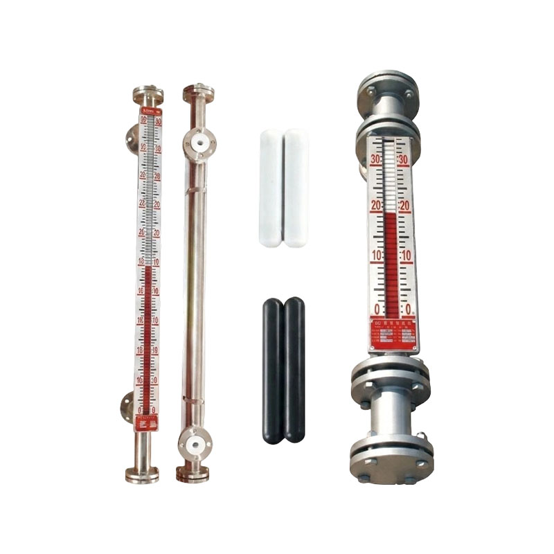
UZC-A03F anti-corrosion magnetic level gauge
Liquid-level measurement in corrosive service presents several simultaneous challenges. The first is chemical compatibility. A material that performs well in water or neutral oil may deteriorate rapidly in hydrochloric acid, sulfuric acid, caustic solution, oxidizing chemicals, or chloride-containing wastewater. Corrosion can weaken a chamber, damage seals, cause leakage, or change the dimensions of internal components.
The second challenge is measurement reliability. A level instrument installed on a chemical tank may be exposed to vapors, condensation, suspended solids, temperature changes, and pressure fluctuations. If the measuring principle depends on exposed electrical contacts or electrodes immersed directly in the process liquid, deposits and chemical attack can affect the signal. Mechanical parts may also become stuck when solids accumulate inside the measuring chamber.
The third challenge is operational safety. Many corrosive liquids can injure personnel and damage nearby equipment if released. A level gauge that requires frequent disassembly, has exposed moving components, or uses a fragile transparent tube can increase maintenance risk. An effective design should keep the process medium isolated, make the indication easy to read, and allow inspection without unnecessary contact with the liquid.
The UZC-A03F addresses these requirements by separating the liquid-contacting chamber from the external indication and transmission components. The float moves inside the protected chamber with the liquid level. Its magnetic field is coupled through the chamber wall to an external magnetic flap indicator or transmitter. As a result, the external electrical components do not need to touch the corrosive medium.
The instrument is based on buoyancy and magnetic coupling. A float is installed inside the measuring chamber and selected according to the density of the measured medium and the mechanical design of the gauge. As the liquid rises or falls in the connected tank, the liquid level in the chamber changes correspondingly. The float follows this movement.
A magnet or magnetic assembly inside the float generates a magnetic field. Outside the chamber, magnetic flaps, a magnetic indicator, or a compatible remote transmitter responds to this field. The external indicator changes position as the float moves, producing a visible representation of liquid height. Because the indicator is magnetically coupled rather than mechanically connected through an open shaft, there is no conventional external penetration that must transmit movement from the corrosive interior.
This principle provides a clear separation between measurement and process containment. The liquid remains within the chamber and connected vessel piping, while the operator reads the level from outside. The design also supports the addition of limit switches and a two-wire 4–20 mA transmitter. These accessories extend the instrument from a local indicator into a complete level monitoring and alarm solution.
The magnetic coupling is non-contact from the perspective of the external components. The electrical transmitter and optional switches are positioned outside the corrosive liquid path. This arrangement reduces the possibility of corrosion-related electrical failure and helps maintain signal stability in applications where immersed electrodes or probes would be unsuitable.
The most important characteristic of this level gauge is its adaptation to aggressive media. The chamber may be produced from PP or PVC for suitable low-temperature chemical applications. For more demanding mechanical or chemical conditions, a stainless-steel body can be lined with PP, PTFE, or other specified materials. The material selection should be based on the chemical composition, concentration, temperature, pressure, and density of the medium.
PTFE is widely valued in chemical processing because of its broad resistance to acids, alkalis, salts, and many organic and inorganic chemicals. A properly selected PTFE lining can provide an effective isolation layer between the structural chamber and the process liquid. PP and PVC can also offer useful corrosion resistance in appropriate temperature ranges and chemical services. The correct material is not determined by the general name of a chemical alone; concentration, temperature, impurities, residence time, and mechanical conditions must also be considered.
The chamber design helps protect the structural parts of the instrument from direct chemical exposure. When the lining is continuous and correctly installed, the process medium is isolated from the stainless-steel support structure. This reduces corrosion damage and can extend service life compared with an unlined metallic chamber.
Material compatibility must nevertheless be confirmed before ordering. PTFE anti-corrosion construction is not suitable for every extreme chemical service. High-temperature molten alkali metals, chlorine trifluoride, and other exceptionally aggressive special media require a specific engineering assessment. Users should provide the exact medium composition, concentration, operating temperature, pressure, density, and any relevant impurities before final material selection.
Many electronic level instruments use probes, electrodes, or sensors that are installed directly in the liquid. Such components can be affected by chemical attack, deposits, coating, conductivity changes, and insulation failure. The UZC-A03F uses magnetic transmission so that the external transmitter and switches remain outside the process medium. This substantially reduces the exposure of electrical components to corrosive liquids.
A magnetic flap indicator provides a direct visual indication at the tank. Operators can observe the liquid height without opening the vessel, removing a cover, or relying exclusively on a control-room display. This is useful during filling, draining, transfer, dosing, and troubleshooting operations.
A conventional sight glass can show the local level but normally cannot send a signal to a control system. The UZC-A03F can be equipped with an XG/UQZ-08 two-wire transmitter that delivers a 4–20 mA DC output. This signal can be connected to a PLC, distributed control system, recorder, digital indicator, or alarm unit. The same installation can therefore support local observation and remote supervision.
Upper- and lower-limit level switches can be added to provide alarm or interlock functions. A high-level switch may warn operators before a tank overflows, while a low-level switch may protect a pump from dry running or identify the need for replenishment. These switches can also be integrated into filling and discharge control sequences, subject to the electrical design of the installation.
The fully enclosed structure and corrosion-resistant isolation layer help reduce the risk of liquid leakage through exposed transmission components. Unlike an open mechanical linkage, the magnetic coupling does not require a sliding external shaft or an exposed rotating connection. This contributes to improved containment and reduced maintenance exposure.
The standard measuring range extends from 300 to 6000 millimeters. This makes the instrument suitable for both relatively compact process tanks and taller storage vessels. The measuring range is specified according to the actual tank dimensions, connection positions, float characteristics, and required indication scale.
The following table summarizes the principal technical characteristics and selection considerations.
| Parameter | Typical Specification or Option | Engineering Consideration |
|---|---|---|
| Measuring range | 300–6000 mm | Selected according to tank height and connection locations |
| Accuracy | ±10 mm | Depends on float movement, installation, medium properties, and calibration |
| Chamber material | PP, PVC, or stainless steel lined with PTFE | Must be matched to chemical compatibility and mechanical requirements |
| Operating pressure | Up to 1.0 MPa | Actual pressure rating depends on construction and configuration |
| Temperature range | Generally -20°C to 120°C for PTFE-limited service; selected configurations may be specified up to 150°C | High-temperature service requires confirmation before manufacture |
| Minimum medium specific gravity | ≥0.45 g/cm³ | Required for proper float buoyancy |
| Minimum density difference | ≥0.15 g/cm³ | Important where multiple liquid phases or interface conditions exist |
| Medium viscosity | ≤0.02 Pa·s | High viscosity can slow float response or increase friction |
| Remote output | 4–20 mA DC, two-wire transmitter option | Suitable for standard industrial control systems |
| Connection flanges | DN20, DN25, and other options | Flange standard and dimensions must match the tank nozzle |
| Alarm function | Optional upper- and lower-limit switches | Used for warning, interlock, or automatic control |
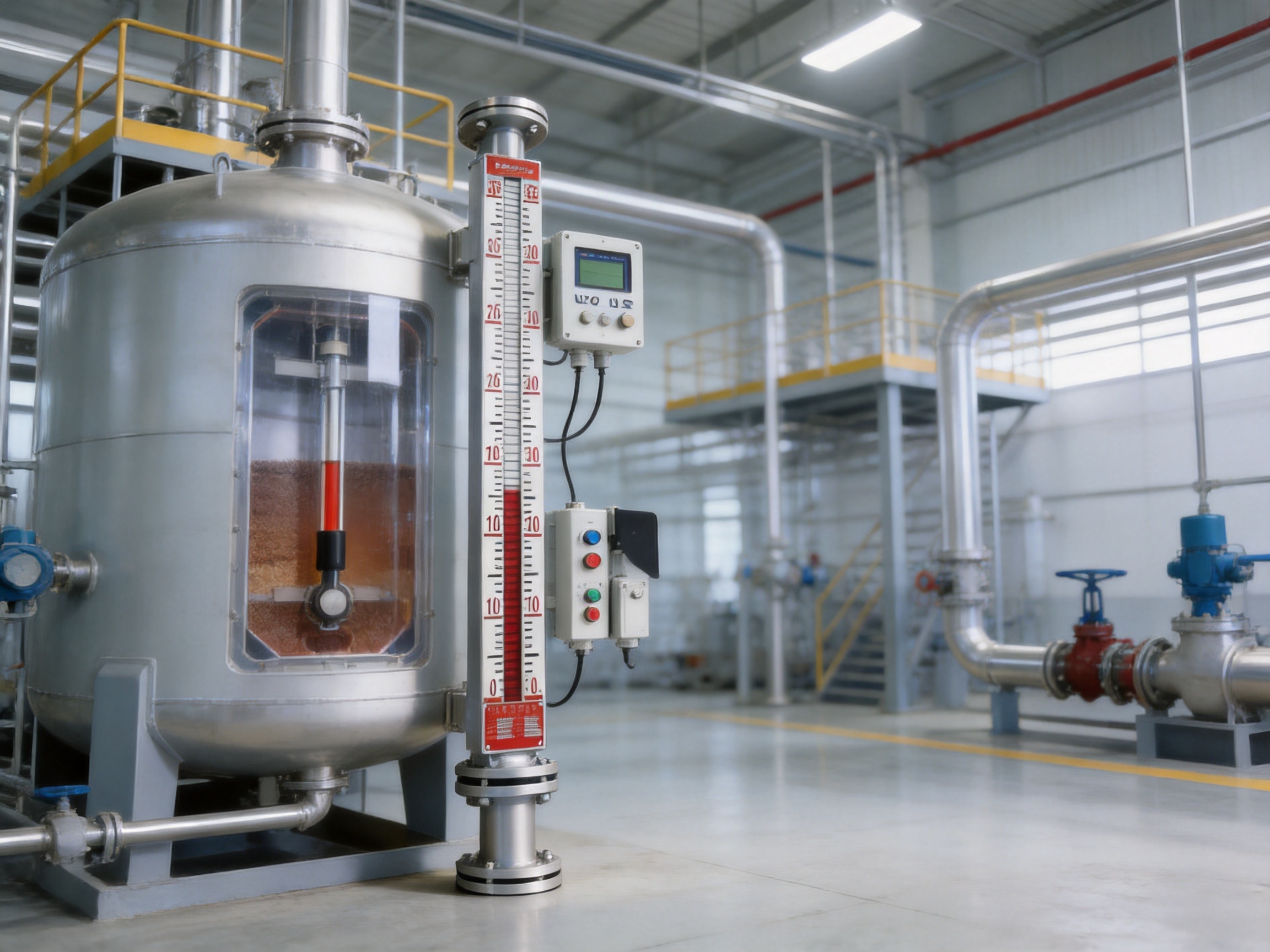
Chemical plants frequently use storage tanks for hydrochloric acid, nitric acid, sulfuric acid, sodium hydroxide, potassium hydroxide, sodium hypochlorite, chemical additives, and intermediate solutions. In these services, level information is needed to manage inventory, prevent overflow, schedule replenishment, and maintain stable process conditions.
The UZC-A03F can be applied to acid and alkali storage tanks, reaction vessels, neutralization tanks, and raw-material containers when the selected chamber and lining materials are compatible with the medium. The external magnetic indication allows personnel to check the level from a safe position, while a remote transmitter can deliver continuous data to the plant control room.
In a neutralization system, for example, the level gauge can monitor an acidic or alkaline dosing tank. A lower-limit switch may indicate that the tank needs replenishment, while a high-level switch can stop a transfer pump or close an inlet valve. The 4–20 mA signal can be used by the control system to calculate remaining capacity and regulate chemical dosing.
For chemical raw-material storage, the long measuring range and optional alarm functions can help improve operating discipline. Operators can establish high and low operating limits and receive an early warning before the tank reaches an unsafe or operationally inconvenient level.
Wastewater treatment facilities often handle liquids containing acids, alkalis, dissolved salts, suspended solids, and corrosive process residues. Examples include chemical dosing tanks, pH adjustment tanks, wastewater equalization tanks, electroplating waste tanks, sludge conditioning systems, and contaminated drainage vessels.
Level measurement in these systems must account for the possibility of fouling and suspended material. A large amount of solid impurity can obstruct the float or interfere with movement inside the chamber. For this reason, a filter or suitable upstream separation device is recommended when the medium contains significant solids. Regular inspection should also be included in the maintenance plan.
The sealed design is particularly useful in wastewater areas where splashing, corrosive vapors, and high humidity can damage exposed equipment. Since the external indicator and transmitter do not directly contact the liquid, the instrument can offer a practical alternative to immersed electrical probes in selected services.
Remote transmission is valuable in wastewater plants because tanks may be distributed across large sites or located in areas that are difficult to access frequently. A control-room operator can observe the continuous level signal while local personnel use the magnetic indicator during inspection and maintenance.
Pharmaceutical production requires controlled handling of process liquids, cleaning chemicals, acidic solutions, alkaline solutions, and specialty reagents. Level instruments must be selected not only for accuracy but also for material compatibility, cleanability, installation suitability, and process safety.
The UZC-A03F can be used for compatible corrosive-liquid storage tanks, ingredient tanks, and acid-base process vessels. The specific chamber material, lining, surface condition, flange arrangement, and accessories should be confirmed against the pharmaceutical facility's process and hygiene requirements.
In support utilities and chemical preparation systems, the gauge can provide a robust local indication while the transmitter sends level data to a supervisory system. Upper- and lower-level switches may support automated replenishment or prevent the operation of transfer equipment under unsuitable conditions.
Because the instrument is available in customized configurations, the customer can specify measuring range, connection size, pressure, density, transmitter arrangement, and alarm requirements. This approach is more appropriate than selecting a generic instrument without considering the actual chemical service.
Pickling, electroplating, metal cleaning, and surface-treatment operations commonly use strong acids, alkaline cleaners, and corrosive salt solutions. Tanks may operate continuously and may be exposed to vapors, droplets, temperature variations, and contamination from metal-processing operations.
The anti-corrosion chamber and magnetic indication system are suitable for compatible acid pickling tanks, electroplating tanks, and corrosive salt storage tanks. A local visual indicator can help operators quickly check process conditions from the tank platform, while remote output can be used for production monitoring and alarm management.
Surface-treatment plants often have several tanks arranged in sequence. A consistent level instrument design can simplify maintenance, spare-parts management, and operator training. The UZC-A03F's range of materials and accessories allows different tanks to be configured according to their individual chemical and mechanical conditions.
The optional XG/UQZ-08 two-wire transmitter converts float position into a standard 4–20 mA signal. The 4 mA point generally represents the lower end of the calibrated measuring range, while 20 mA represents the upper end. The exact calibration must be established according to the specified measuring range and installation dimensions.
A standard current signal is widely used in industrial automation because it is comparatively resistant to electrical noise over long cable runs and can be monitored by many types of control equipment. It can be connected to a control panel, PLC input module, distributed control system, chart recorder, digital display, or data-acquisition unit.
The transmitter option also supports remote trend analysis. A control system can record the level over time, identify abnormal filling or discharge rates, and generate notifications when the level changes unexpectedly. This can assist with leak detection, pump-performance evaluation, inventory management, and preventive maintenance.
Where limit switches are installed, the level gauge can provide discrete high- and low-level signals in addition to the continuous analog output. This combination is useful because the analog signal gives process visibility, while the switches provide independent threshold actions. The final wiring, switch rating, alarm logic, and control-system interface should be designed by qualified electrical personnel.
Reliable performance in corrosive service depends on more than the basic operating principle. It also depends on material preparation, lining quality, dimensional accuracy, welding or assembly control, float manufacture, magnetic component quality, calibration, and final inspection. Xinguo Group Co., Ltd. manufactures industrial instrumentation and related alloy, cable, and material products through an integrated organization that includes instrument manufacturing, alloy production, cable production, and precious-metal activities.
The group was established in 1997 and is located in Tianchang City, Anhui Province, China. It has a registered capital of RMB 118 million, a land area of more than 150 mu, and a construction area of approximately 60,000 square meters. The organization employs nearly 300 people, including more than 50 professional technicians, senior technical experts, senior engineers, engineers, and assistant engineers.
This technical workforce supports product development, process improvement, material selection, production engineering, and quality control. For an anti-corrosion level gauge, engineering experience is particularly important because the instrument must be configured around the process medium rather than treated as a one-size-fits-all product.
The company uses modern quality management systems and has obtained ISO9001 Quality Management System, ISO14001 Environmental Management System, and GB/T28001 Occupational Health and Safety Management System certifications. These systems provide a structured basis for controlling production activities, documenting procedures, monitoring quality, managing environmental responsibilities, and improving workplace safety.
Manufacturing begins with a review of the customer's process data. Important inputs include medium composition, concentration, temperature, pressure, specific gravity, viscosity, solid content, measuring range, flange standard, and output requirements. This information guides the selection of PP, PVC, PTFE-lined stainless steel, float material, sealing components, transmitter type, and alarm accessories.
A disciplined review process reduces the possibility of selecting an unsuitable lining or float. It also helps identify applications that require special engineering approval, such as unusually high temperature, high pressure, extreme chemical concentration, or unusual density conditions.
The measuring chamber must maintain dimensional stability and reliable pressure containment. Depending on the configuration, fabrication may involve preparation of a polymer chamber, assembly of lined metallic components, flange machining, connection welding, lining installation, and fitting of internal float components.
Dimensional control is important because the float must move freely while remaining correctly coupled to the external magnetic indicator. Misalignment, local deformation, excessive internal roughness, or lining bulging can restrict float movement. Careful assembly and inspection help maintain smooth operation over the full range.
The anti-corrosion layer is a critical barrier between the process medium and the structural body. It must be continuous, properly supported, and free from scratches, cracks, pinholes, or installation damage. Sealing areas and flange interfaces require particular attention because leakage often begins at discontinuities or improperly compressed gaskets.
During handling and installation, the lining should be protected from hard tools and sharp objects. The user should not strike the chamber body, use abrasive cleaning methods, or drag the instrument across rough surfaces. A damaged lining can compromise chemical resistance even if the external structure appears intact.
The float must be compatible with the medium and have sufficient buoyancy. The stated minimum medium specific gravity is 0.45 g/cm³, with a recommended density difference of at least 0.15 g/cm³ for the applicable measurement condition. The magnetic assembly must produce a stable coupling field across the chamber wall and remain correctly oriented during operation.
Factory inspection should verify float movement, magnetic indication, measuring range, switch position, transmitter response, and connection integrity. Calibration and functional tests are especially important when the gauge includes a remote transmitter or limit switches.
Quality control should include verification of dimensions, materials, flange configuration, pressure-related requirements, visual condition, magnetic flap response, output signal, and accessory installation. Customer-specific documentation may include a product data sheet, connection information, calibration details, inspection records, and installation instructions.
The company states that its products comply with IEC international standards as well as applicable national and industrial specifications. Compliance requirements depend on the ordered configuration and destination market, so the relevant standards, certificates, and inspection documents should be confirmed during the technical quotation stage.
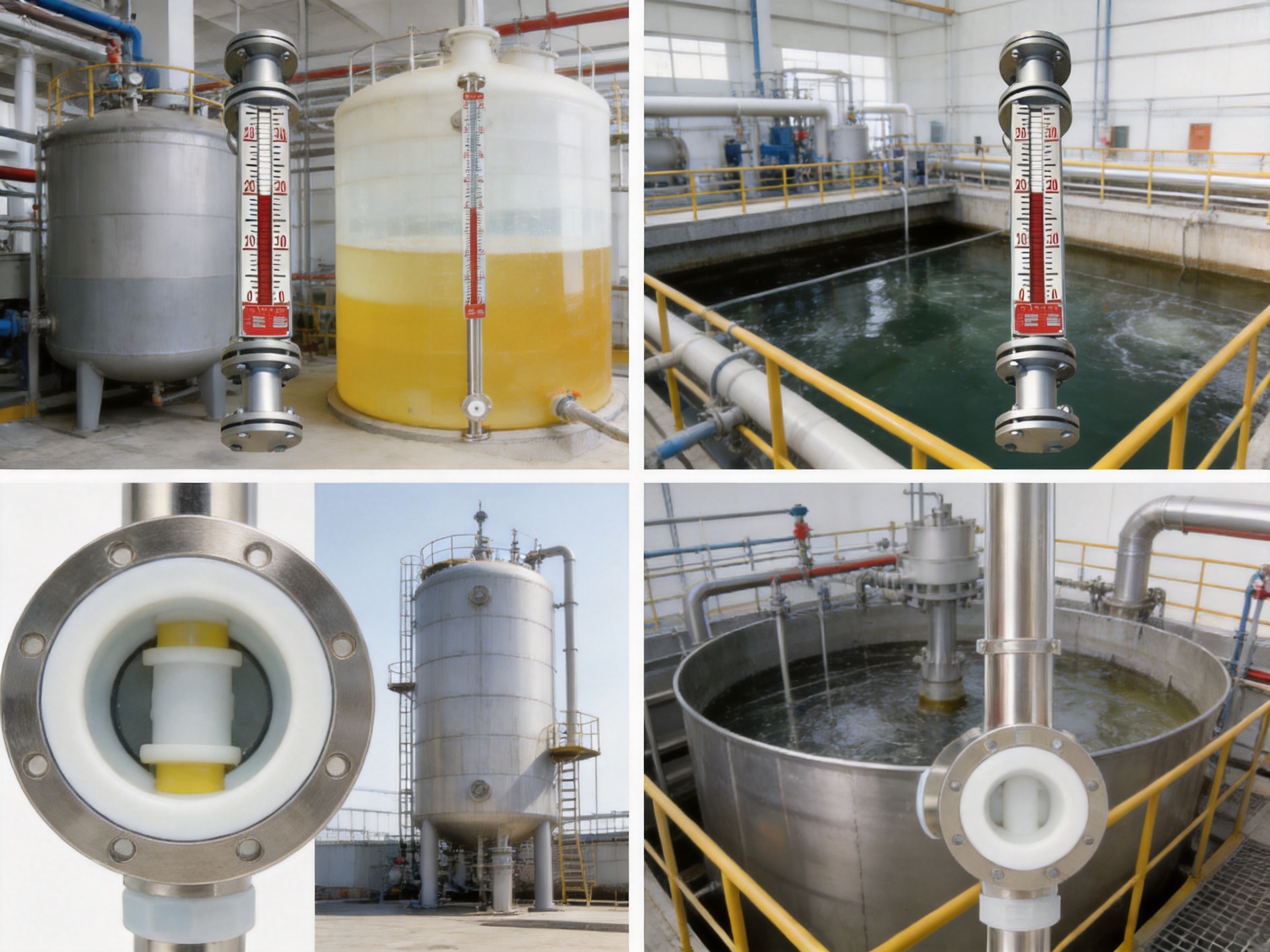
The anti-corrosion magnetic level gauge must be installed vertically. Vertical installation allows the float to rise and fall freely and ensures that the external magnetic indicator corresponds correctly to liquid height. The tank nozzles should be aligned so that the chamber is not forced into a stressed or tilted position during bolting.
The inlet and outlet connections should be connected according to the approved piping arrangement. Isolation valves may be installed to facilitate maintenance, but they must be selected for the measured medium and pressure. When the instrument is commissioned, the inlet and outlet valves should be opened slowly. Rapid pressurization can create pressure shock and may damage the lining, seals, or float assembly.
The chamber should be checked for foreign objects before operation. Hard tools must not be inserted into the measuring tube, and the lining must not be scratched. If the medium contains a large amount of solid impurity, a filter or upstream separator is recommended. The filter should be selected so that it does not cause an unacceptable pressure drop or become a maintenance bottleneck.
The gauge should be installed where the magnetic indicator can be read safely and where the transmitter and switches can be accessed for inspection. Excessive vibration, impact, strong external magnetic fields, and locations exposed to mechanical damage should be avoided. Electrical wiring must be routed and terminated according to the transmitter and switch specifications.
Routine maintenance begins with visual inspection. Operators should check whether the magnetic flap indicator changes smoothly as the process level changes, whether the displayed level corresponds reasonably with the control-room value, and whether there are signs of leakage, lining damage, abnormal corrosion, or flange seepage.
If the indication does not change, the first possibility is that the float has become stuck because of impurities. Another possibility is deformation or bulging of the internal lining, which can reduce the clearance around the float. Magnetic steel demagnetization is a further possible cause. These conditions should be investigated systematically.
The instrument body must never be struck to force the indicator to move. Impact may damage the chamber, deform the lining, displace the float, or weaken the magnetic assembly. If contamination is suspected, the gauge should be isolated, depressurized, drained, and cleaned according to the facility's safety procedures.
For installations with a remote transmitter, the 4–20 mA output should be compared periodically with the local indication and an approved reference measurement. Sudden signal changes, a fixed output, an out-of-range value, or disagreement between local and remote indications may indicate a transmitter, wiring, calibration, or float-movement problem.
Alarm switches should be tested according to the facility's functional-safety and process-control procedures. Testing should confirm the actual switch action, alarm response, interlock response, and return to normal operation. The test interval depends on the process risk and the plant maintenance policy.
Correct selection requires more than choosing a nominal pipe size. The customer should provide the following information before the product is configured: measured medium, chemical composition, concentration, temperature, operating pressure, specific gravity, viscosity, expected solids, tank height, required measuring range, connection size, flange standard, local indication requirements, transmitter requirements, alarm points, and any special environmental or certification requirements.
The specified pressure capability is up to 1.0 MPa for applicable configurations, but the actual permissible pressure depends on chamber construction, lining, flange design, temperature, and ordered accessories. Similarly, the general PTFE-limited operating temperature is commonly stated as -20°C to 120°C, while some product specifications may identify a range up to 150°C for selected constructions. High-temperature or high-pressure corrosive service must be reviewed and confirmed by the manufacturer before production.
Density and viscosity are also important. The float must have adequate buoyancy in the liquid. A very low-density medium may not provide enough lifting force for a standard float, while high viscosity can slow movement or increase resistance. Suspended particles can cause sticking, so filtration and maintenance access should be considered during system design.
The selected flange standard must match the tank nozzle. The product can be supplied with DN20, DN25, and other connection options, with HG/T 20592-2009 identified as an applicable flange standard. The complete flange specification, sealing face, pressure class, bolt arrangement, and gasket material should be checked before installation.
It is intended for compatible corrosive liquids, including many acidic, alkaline, saline, chemical, wastewater, pickling, and electroplating solutions. The exact suitability depends on the composition, concentration, temperature, pressure, density, viscosity, and impurities of the medium. Material compatibility must be confirmed before ordering.
No. PTFE, PP, PVC, and other materials each have specific chemical and temperature limits. PTFE should not automatically be assumed suitable for high-temperature molten alkali metals, chlorine trifluoride, or other highly corrosive special media. The customer should submit complete process data for an engineering compatibility review.
Possible causes include impurities that have trapped the float, lining deformation or bulging, an incorrectly installed chamber, excessive viscosity, or demagnetization of the magnetic steel. The instrument should be isolated safely before inspection. Operators must not strike the body to make the indicator move.
For PTFE-limited service, the general operating range is approximately -20°C to 120°C. Some configurations may be specified for temperatures up to 150°C, depending on materials and design. High-temperature applications require confirmation of the complete assembled instrument rather than relying only on the nominal lining material limit.
The stated operating pressure is up to 1.0 MPa for applicable configurations. The final pressure rating depends on chamber material, lining, flange design, temperature, dimensions, and accessories. High-pressure corrosive service should be reviewed and customized with the manufacturer.
Product: UZC-A03F anti-corrosion magnetic level gauge


 INQUIRY
 English
 عربى
 русский
 中文简体