In industrial process measurement, the pressure gauge is often the first instrument operators consult when they need to understand what is happening inside a pipeline, vessel, pump, filter, or processing unit. A gauge must therefore do more than indicate a numerical value. It must remain readable, stable, and dependable when the measured medium is corrosive, viscous, contaminated, prone to crystallization, or present only at a very low pressure. The XG/YPF series diaphragm pressure gauge is designed for these demanding conditions through a direct diaphragm sensing structure that separates the measured medium from the internal movement while avoiding the narrow pressure passages found in many conventional instruments.
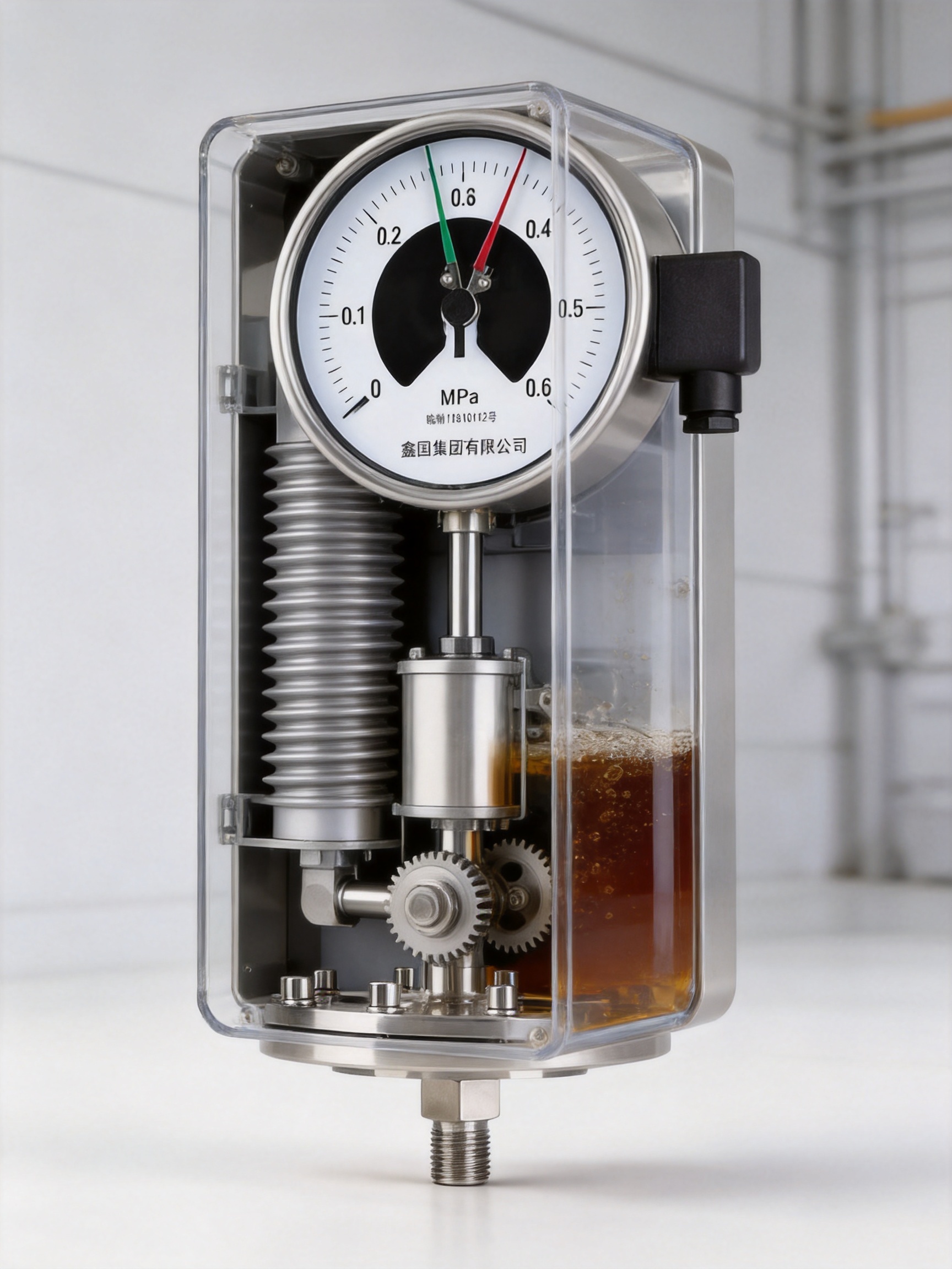
This product is a local-indication pressure gauge using a corrugated diaphragm as its pressure-sensitive elastic element. The measured gas or liquid acts directly on the diaphragm. Pressure causes controlled displacement of the corrugated membrane, and a connecting rod and gear transmission mechanism amplifies this movement to drive a pointer across the dial. Because the process medium is isolated from the movement, the internal mechanism is protected from corrosion, contamination, and deposits.
The design is particularly suitable for process applications involving viscous liquids, media containing suspended impurities, liquids that may precipitate, and corrosive gases or liquids. It is also appropriate for micro-pressure and low-pressure measurement, where the sensitivity of a diaphragm can provide a practical advantage over pressure elements intended primarily for higher-pressure service. With selectable diaphragm materials, optional alarm contacts, and shock-resistant configurations, the gauge can be adapted to a broad range of industrial measurement requirements.
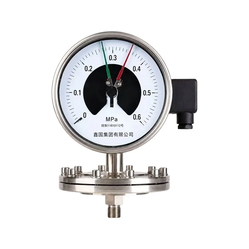
XG/YPF series diaphragm pressure gauge
The XG/YPF series is a mechanical local pressure indicator. Unlike an electronic pressure transmitter, it does not require an external power supply, signal cable, digital display, or control system to provide a visible pressure reading. Its pointer and dial provide immediate information at the installation point, making the instrument useful for routine inspection, equipment adjustment, commissioning, and safety observation.
The central sensing component is a corrugated diaphragm. A diaphragm is a thin, flexible membrane formed with controlled folds or corrugations. These corrugations increase the membrane’s ability to move under pressure while maintaining predictable elastic behavior. When pressure is applied to one side, the diaphragm deflects. The amount of deflection corresponds to the pressure within the specified measuring range.
Mechanical movement transfers the diaphragm displacement to the pointer. The connecting rod receives the diaphragm movement, while the transmission mechanism converts and amplifies the movement into angular pointer rotation. The dial is marked with the selected pressure scale, allowing the operator to read the local value without opening the case or contacting the process medium.
The process medium directly contacts the pressure-bearing diaphragm, but it does not enter the movement chamber. This separation is an important feature. In a conventional pressure gauge, the sensing element and internal passages may be vulnerable to blockage or corrosion when exposed to difficult media. In the diaphragm design, the pressure is transmitted through the movement of the membrane rather than through a small internal channel filled with the process fluid.
The gauge consists principally of the measuring diaphragm, the joint or flange connection, the connecting rod transmission mechanism, and the protective case. The pressure-bearing part is selected according to the model and range. The case protects the dial and movement from normal environmental exposure, while the IP64 enclosure rating provides protection against dust ingress sufficient to interfere with operation and against water splashes from different directions.
Vertical mounting is the specified working position. Correct installation is important because the mechanical movement, pointer balance, and diaphragm response are calibrated in this orientation. A gauge should be installed where the dial can be read easily, where the connection is not exposed to excessive mechanical stress, and where the surrounding temperature remains within the rated range.
Pressure measurement becomes more complicated when the medium is not clean, free flowing, chemically neutral, or sufficiently pressurized to produce a large sensing movement. A gauge designed for general-purpose air or water service may perform poorly when connected to a process containing fibers, crystals, sludge, high-viscosity fluid, corrosive chemicals, or low-pressure gas.
The diaphragm structure addresses these limitations by using a broad pressure-sensitive surface instead of a narrow sensing passage. The medium acts on the membrane, and the membrane transmits pressure through mechanical displacement. This arrangement reduces the likelihood that solid particles, viscous material, or crystallized deposits will become trapped inside a small passage and prevent the pointer from responding.
The absence of a small internal flow channel is one of the main competitive advantages of this type of gauge. A conventional instrument may be affected by a blocked inlet or restricted pressure path. Once the path is blocked, the instrument may continue to display an old pressure value, respond slowly, or remain fixed while the actual process pressure changes. The diaphragm design is better suited to media that would create these problems.
Another advantage is the ability to respond to low pressure. A diaphragm can be manufactured with a geometry and material combination that provides sensitive movement under relatively small pressure changes. This makes the gauge suitable for low-pressure gas systems, ventilation and extraction equipment, filter monitoring, low-pressure liquid lines, and other applications where the measured pressure is below the practical range of many standard spring tube gauges.
Corrosion resistance can also be improved by selecting an appropriate diaphragm material. Available options include 316 or 316L stainless steel, Hastelloy, and PTFE-related protective solutions, depending on the exact construction and application requirements. Material selection must consider the chemical composition, concentration, temperature, pressure range, and duration of contact with the medium. A material that performs well with one chemical may be unsuitable for another.
The process medium is isolated from the internal movement. This protects gears, shafts, pivots, and other mechanical components from direct exposure. The result is a more stable measurement system in applications where ordinary internal mechanisms would be attacked by the medium or contaminated by deposits.
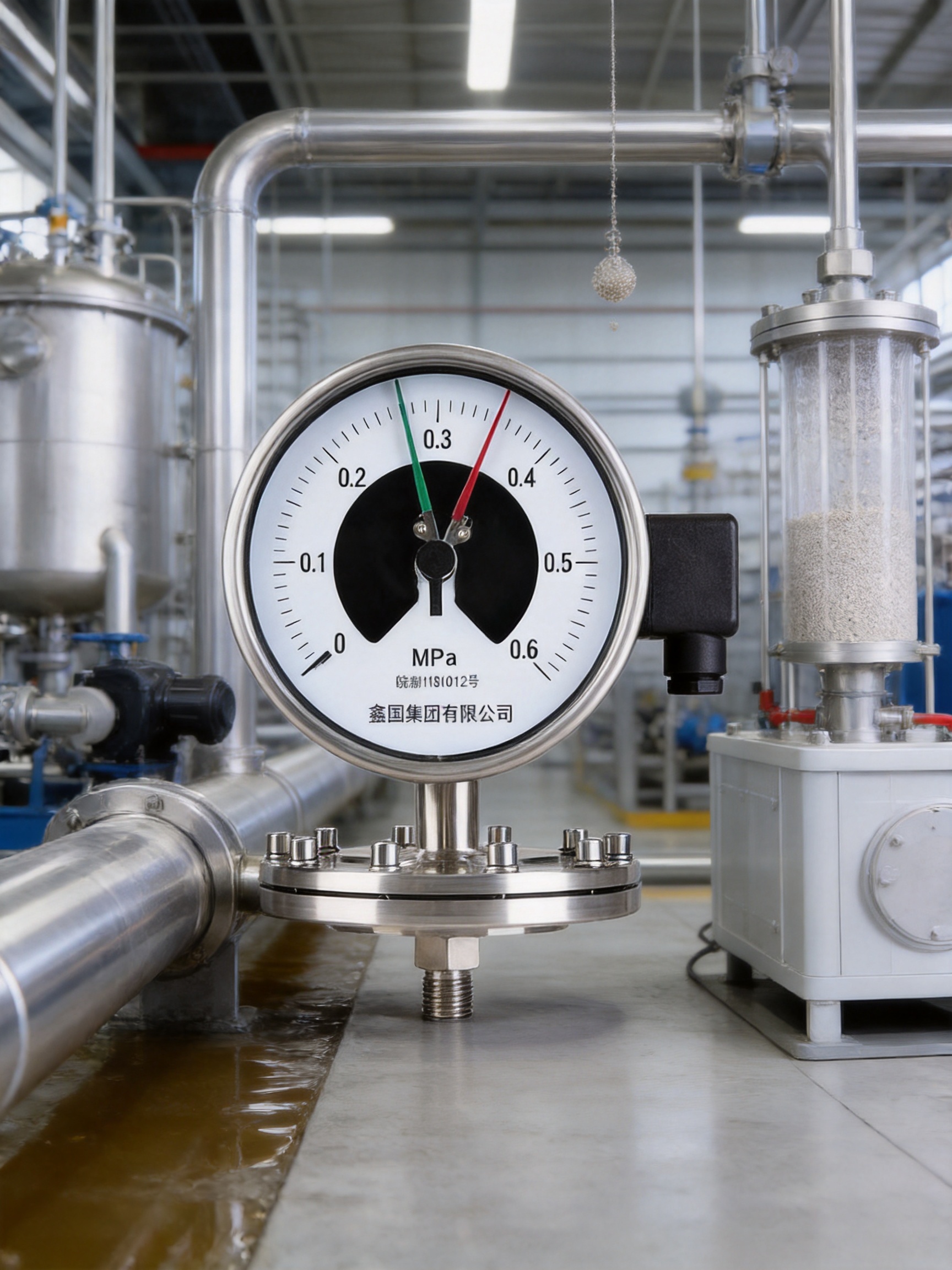
The most visible advantage is the strong resistance to clogging. The diaphragm responds across its pressure-bearing surface instead of depending on a narrow flow path. This is valuable when measuring liquids containing suspended solids, granular material, fibers, sediment, or precipitated compounds.
In practical operation, blockage can be more damaging than a simple loss of accuracy. A blocked gauge may appear normal while failing to show a pressure increase caused by a filter becoming obstructed, a valve closing, or a pump operating outside its intended condition. By reducing the structural causes of blockage, the diaphragm gauge helps maintain a more direct relationship between process pressure and pointer movement.
The gauge is not immune to every form of fouling. Thick deposits may still accumulate on an exposed diaphragm, and hard particles may cause erosion over long periods. However, the open and comparatively simple pressure-bearing structure is generally more suitable for difficult media than a small-bore pressure path.
Low-pressure measurement requires a pressure element capable of producing a readable movement without excessive friction or mechanical resistance. The corrugated diaphragm is sensitive to small pressure changes and can be configured for micro-pressure, low-pressure, vacuum, and compound pressure service within the listed ranges.
This sensitivity is useful for monitoring pressure differences in gas handling equipment, low-pressure process lines, environmental systems, tanks, and equipment where small changes indicate a developing operating problem. A gauge that responds quickly to a small pressure change can help operators detect blocked filters, insufficient ventilation, line restrictions, and unstable process conditions earlier.
The instrument should nevertheless be selected within an appropriate range. Low-pressure sensitivity does not mean that the gauge can safely measure any pressure. A diaphragm has a defined elastic limit. Persistent overpressure or repeated severe pressure shocks can cause permanent deformation, zero shift, or loss of accuracy.
Corrosive media can attack a pressure element, process connection, case components, or movement. The diaphragm is the first barrier between the medium and the gauge mechanism, so its material is especially important. Stainless steel options provide a practical solution for many industrial fluids, while Hastelloy can be considered for more aggressive chemical environments. PTFE-based protection may be appropriate where chemical resistance is more important than high mechanical strength.
Material selection should never be based solely on the word “corrosive.” The user should provide the full medium name, concentration, temperature, pressure, possible contaminants, and any cleaning chemicals used during operation. The manufacturer or qualified engineering team can then evaluate the compatibility of the diaphragm and wetted parts.
The diaphragm construction has good overload capability for its intended pressure range. It can tolerate certain short-term pressure fluctuations and instantaneous impacts better than some delicate pressure elements. This characteristic contributes to operational reliability in systems where pumps start and stop, valves open rapidly, or process pressure changes occur over a short period.
Good overload performance should not be interpreted as permission to operate outside the specified range. Repeated or excessive overpressure may still deform the membrane. Pressure pulsation, water hammer, vibration, and rapid cycling should be evaluated during selection. Where necessary, a suitable damping arrangement, pulsation restrictor, or protective installation method should be considered.
The basic version provides local indication, but the product can also be paired with electric contact heads for alarm or control functions. A distribution contact can be configured to initiate an alarm when the pointer reaches a defined pressure position, subject to the selected contact arrangement and electrical requirements.
A shock-resistant configuration is also available for applications where mechanical vibration or pressure pulsation may influence pointer stability. This gives users more flexibility than a basic visual gauge alone. Instead of replacing the entire instrument when an application changes, the gauge can be selected with a function suited to the operating environment.
Simple construction also supports practical maintenance. The instrument can be inspected, calibrated, or replaced without the complexity associated with powered electronic devices. In facilities where local serviceability is important, this can reduce troubleshooting time and simplify inventory planning.
The XG/YPF series is intended for measuring gases and liquids that may be corrosive, viscous, contaminated, or not easy to crystallize. Typical application decisions should consider both the behavior of the medium and the pressure range. The gauge is especially suitable when the medium would create a blockage risk for a small pressure inlet or when the internal movement needs protection from direct contact.
In chemical processing, the gauge can be used on compatible corrosive liquids and gases when the diaphragm material and pressure-bearing components are selected correctly. Local indication can help operators observe reactor pressure, storage vessel pressure, transfer line pressure, or utility pressure without relying on a remote display.
In wastewater and environmental systems, suspended particles and deposits can make ordinary gauges unreliable. A diaphragm gauge may be considered for sludge-related systems, treatment equipment, low-pressure gas lines, and filter monitoring, provided that the diaphragm is protected from severe abrasion and the connection is appropriate for the installation.
In food, pharmaceutical, and hygienic processing, the instrument must be evaluated against the required cleanability, surface finish, connection standard, and regulatory expectations. The diaphragm principle can be beneficial because it reduces the possibility of process fluid entering the movement, but the complete wetted construction must satisfy the application requirements.
In pulp, paper, fiber, and pigment-related processes, the medium may contain material that could block narrow pressure passages. The diaphragm’s broad sensing surface and anti-blocking characteristics provide a useful alternative for local pressure observation.
In vacuum and compound-pressure service, the selected range must correspond to the actual operating condition. The available ranges include negative pressure and combined vacuum-pressure scales. The operator should ensure that the expected vacuum, positive pressure, and transient conditions remain within the selected scale.
In pump and pipeline applications, the gauge may be used to observe suction, discharge, or intermediate pressure. However, pulsation and vibration should be considered. A shock-resistant model or suitable installation arrangement may be preferred where the pointer would otherwise oscillate or the movement could be subjected to repeated mechanical impact.
Correct range selection is essential for both safety and readability. A pressure gauge should not operate continuously at the extreme end of its scale. The normal operating pressure should generally fall within a central portion of the dial so that the pointer movement remains readable and there is sufficient capacity for process variation.
The product family includes models with different dial sizes and pressure-bearing dimensions. The listed model families include XG-YPF-100A, XG-YPF-100B, XG-YPF-100B-F, XG-YPF-150A, XG-YPF-150B, and XG-YPF-150B-F. The letter and number combinations identify different structural or dimensional configurations, while the exact selection should be confirmed against connection requirements, dial size, pressure range, and optional functions.
Available scale categories include low positive pressure, higher positive pressure, vacuum, compound pressure, and kilopascal ranges. Examples include 0 to 0.06 MPa, 0 to 0.1 MPa, 0 to 0.16 MPa, 0 to 0.25 MPa, 0 to 0.4 MPa, 0 to 0.6 MPa, 0 to 1 MPa, 0 to 1.6 MPa, and 0 to 2.5 MPa. Higher ranges include values such as 0 to 4 MPa, 0 to 6 MPa, 0 to 10 MPa, 0 to 16 MPa, 0 to 25 MPa, and 0 to 40 MPa for applicable configurations.
Vacuum and compound ranges include options such as negative 0.1 to zero MPa, negative 0.1 to positive 0.1 MPa, negative 0.1 to positive 0.15 MPa, negative 0.1 to positive 0.3 MPa, negative 0.1 to positive 0.5 MPa, negative 0.1 to positive 0.9 MPa, negative 0.1 to positive 1.5 MPa, and negative 0.1 to positive 2.4 MPa. Other configurations cover ranges expressed in kilopascals, including low positive, low negative, and symmetrical compound scales.
| Selection Item | Available or Specified Information | Selection Consideration |
| Pressure element | Corrugated diaphragm | Suitable for direct pressure sensing in difficult media |
| Accuracy class | 2.5 | Confirm whether this accuracy is suitable for the process and control requirement |
| Dial and body configuration | Several model families and dimensional configurations | Select according to visibility, connection arrangement, and installation space |
| Positive pressure ranges | From low-pressure ranges to higher ranges up to applicable 40 MPa configurations | Choose a scale that covers normal pressure and transient conditions |
| Vacuum and compound ranges | Vacuum, positive, and combined vacuum-positive scales | Match the scale to the actual vacuum and pressure cycle |
| Wetted material | Options may include 316 or 316L, Hastelloy, and PTFE solutions | Verify chemical, temperature, and abrasion compatibility |
| Installation position | Vertical mounting | Install in the specified orientation for proper indication |
| Enclosure protection | IP64 | Use within suitable environmental exposure limits |
| Ambient temperature | Negative 40 to positive 70 degrees Celsius | Consider process heat transfer and outdoor conditions |
The pressure-bearing dimension varies by model and range. The supplied specifications identify dimensions such as 85 millimeters, 115 millimeters, and 160 millimeters for different configurations. One special note identifies the 0 to 40 MPa, negative 40 to zero, and plus or minus 20 kilopascal specifications as using an 85-millimeter pressure-bearing dimension. Final dimensional data should be confirmed before purchase and installation.
The specified accuracy class is 2.5. This means the gauge is intended for general industrial indication rather than highly precise laboratory measurement. Its value lies in dependable local monitoring under difficult process conditions, particularly where resistance to blockage, corrosion, and low-pressure operating conditions is more important than fine laboratory resolution.
The ambient operating temperature is specified as negative 40 to positive 70 degrees Celsius. This broad range supports many indoor and outdoor industrial installations. Even so, the ambient rating is not the same as the temperature rating of the process medium. Heat conducted through the connection can raise the temperature of the diaphragm and movement. If the process is hot, the user should evaluate temperature transfer and consider appropriate installation measures.
Relative humidity is specified at no more than 90 percent. The gauge should be protected from persistent condensation, immersion, and conditions beyond the enclosure rating. An IP64 enclosure is suitable for many dusty industrial environments and splash exposure, but it is not designed for high-pressure washing or continuous water immersion.
The temperature effect is specified as an additional error not exceeding 0.04 percent per degree Celsius when the operating temperature deviates from 20 plus or minus 5 degrees Celsius. This specification helps users evaluate the influence of ambient temperature on measurement performance. For applications requiring tighter accuracy, the expected temperature range should be included in the instrument selection and calibration plan.
Vertical installation is required. The gauge should be mounted on a stable support, and the process connection should not be used to carry excessive pipe stress. Misalignment, vibration, or mechanical loading can affect the movement or cause premature wear. Where the line is subject to strong vibration, a remote mounting arrangement or shock-resistant version may be more appropriate.
A pressure gauge’s field performance depends not only on its basic design but also on the quality of its materials, forming processes, assembly control, calibration, and final inspection. The manufacturer behind this product operates as a diversified industrial group with capabilities covering temperature instruments, pressure instruments, flow meters, level instruments, instrument materials, alloy wire, cables, and related components.
The group was founded in 1997 and operates from Tianchang City in Anhui Province, China. Its manufacturing organization includes instrument production, alloy manufacturing, cable production, precious metal activities, and other specialized units. The reported production base covers more than 150 mu of land, with a construction area of approximately 60,000 square meters and a workforce of nearly 300 people, including more than 50 professional technicians and engineering personnel.
This combination of instrument manufacturing and materials expertise is valuable for diaphragm pressure gauge production. The diaphragm is not an ordinary flat sheet. Its material, thickness, corrugation geometry, forming quality, surface condition, and joining process influence sensitivity, fatigue resistance, corrosion behavior, and repeatability. Experience with alloys and industrial materials can support more informed material selection and process control.
Advanced manufacturing begins with design and engineering review. The intended pressure range, diaphragm material, connection structure, transmission ratio, dial size, case configuration, and optional contact function must be considered as an integrated system. A diaphragm that is suitable for very low pressure may not be appropriate for high-pressure operation, while a material with excellent chemical resistance may require different forming or joining techniques.
Material preparation is another important stage. Correct material identification, dimensional control, surface inspection, and traceability help reduce the risk of using an unsuitable sheet or component. For corrosive service, even a small material error can shorten service life. A disciplined manufacturing system should therefore maintain controlled purchasing, incoming inspection, and batch records for critical wetted materials.
Diaphragm forming must be consistent. Corrugations need controlled geometry so that the pressure-displacement relationship remains predictable. Excessive forming stress, uneven corrugation depth, surface damage, or inconsistent thickness can affect sensitivity and fatigue performance. Production equipment and tooling should be maintained to preserve repeatability from one batch to the next.
The pressure-bearing connection and flange or joint must also be manufactured accurately. A poor sealing surface, incorrect thread, deformation, or welding defect can create leakage or installation problems even when the diaphragm itself is sound. Dimensional inspection and visual inspection are therefore essential during production.
Transmission assembly requires careful control of clearances and alignment. The connecting rod, pivots, gears, pointer shaft, and dial must work together with low friction but without excessive looseness. If the mechanism has too much friction, the pointer may respond slowly or fail to return accurately. If it has excessive clearance, the indication may be unstable or repeatability may decline.
Calibration is a central part of manufacturing. The completed gauge should be compared with reference pressure points over its specified range. Zero position, pointer movement, scale indication, return behavior, and repeatability should be evaluated. Instruments equipped with electric contacts require additional functional checks to verify that the contact changes state at the intended pointer position.
Final inspection should cover appearance, sealing, dial readability, connection dimensions, pointer travel, case condition, and identification markings. Such controls help ensure that the product supplied to the customer matches the selected model and range.
The manufacturer reports the use of modern quality management systems and certifications including ISO 9001 quality management, ISO 14001 environmental management, and GB/T 28001 occupational health and safety management. These systems support documented processes, corrective action, continual improvement, environmental responsibility, and safer production practices.
The company also reports that its products comply with applicable IEC international standards as well as national and industrial specifications. The exact standard applicable to a particular pressure gauge should be confirmed in the technical documentation and purchase specification. Compliance claims should always be matched to the actual model, material, configuration, and destination market.
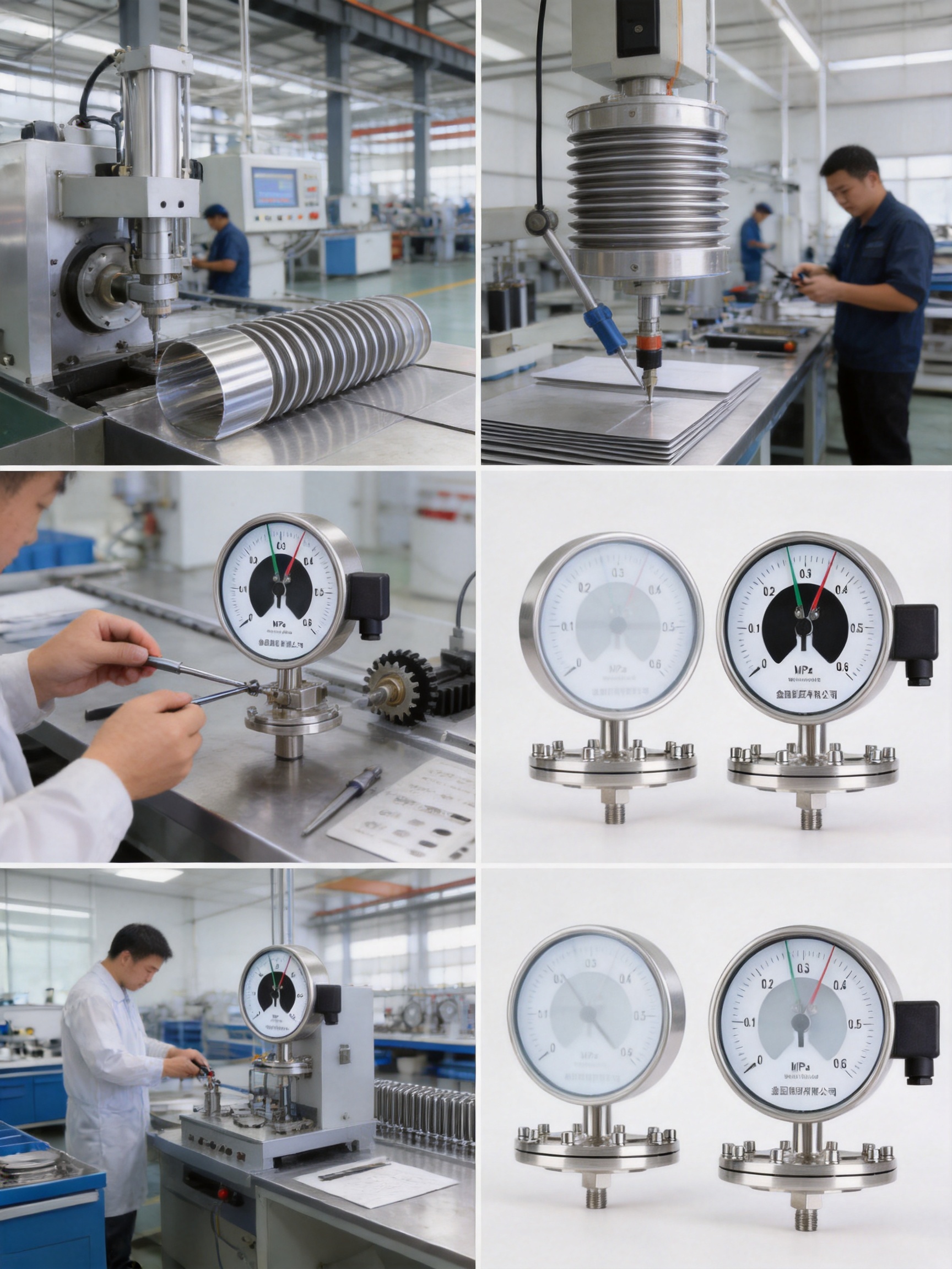
Production begins with understanding the application. The pressure range, medium, temperature, mounting position, vibration, pulsation, environmental exposure, and required functions are reviewed. This step is especially important for diaphragm gauges because the selected diaphragm material and geometry must correspond to the actual process conditions.
Metallic diaphragm materials and other wetted components are selected according to the approved design. Stainless steel grades such as 316 or 316L may be selected for many industrial applications. Hastelloy or PTFE protection may be considered when the chemical environment is more aggressive. Incoming materials should be checked for identification, thickness, surface condition, and conformity with procurement requirements.
The diaphragm is shaped into a controlled corrugated profile. The forming process must provide consistent geometry without creating unacceptable cracks, folds, scratches, or residual deformation. Process parameters, tooling condition, and inspection methods all influence the quality of the pressure element.
The diaphragm is assembled with the joint, flange, or pressure-bearing body. The connection must maintain mechanical strength and sealing integrity throughout the rated range. Depending on the construction, joining and sealing processes may require controlled procedures and inspection to ensure that the diaphragm is not damaged during assembly.
The connecting rod and transmission mechanism are installed after the pressure-sensing assembly is prepared. The movement is adjusted to convert diaphragm displacement into pointer rotation. Low-friction operation, correct alignment, and secure fastening are important for stable indication.
The dial scale is matched to the selected range. The pointer is fitted and positioned at the correct zero reference. The dial must remain clear and readable, with markings that correspond to the measuring range. Any optional contact arrangement is aligned with the pointer position required for the alarm or control function.
Each completed instrument should undergo pressure testing and calibration appropriate to its model. Testing may include zero verification, increasing-pressure points, decreasing-pressure points, repeatability, and visual inspection. Additional tests may be required for sealing, overload behavior, contact operation, or environmental performance.
Products that meet the specified requirements are identified, documented, packaged, and released. Traceability records help connect the finished gauge to its material batch, production process, inspection results, and model information. This is especially useful for industrial customers managing multiple instruments across a large facility.
The gauge should be installed vertically in a position that permits clear reading and safe maintenance. The process connection should match the pipeline or equipment connection without forcing, cross-threading, or applying excessive torque to the case. Pipework should be independently supported so that its weight and vibration are not transferred to the gauge.
Before installation, verify the model, pressure range, diaphragm material, connection size, and optional electrical function. Confirm that the process medium is compatible with every wetted component. If the medium contains sharp particles, consider whether erosion could occur and whether a thicker diaphragm or protective coating is required.
The pressure line should be arranged to reduce the risk of solid accumulation directly on the diaphragm. In systems containing particles or precipitates, the gauge connection should be placed where the pressure represents the process condition without creating a collection pocket. The installation should also allow access for inspection and calibration.
Pressure shocks should be controlled where possible. Rapid valve opening, pump startup, and water hammer can expose the diaphragm to transient pressure substantially above the normal operating value. A suitable restriction, damping device, or operating procedure may help reduce these effects.
For hot media, avoid allowing excessive process heat to reach the movement. Depending on the application, a cooling element, impulse line, or suitable mounting arrangement may be required. The user should confirm the allowable temperature of the complete gauge rather than relying only on the ambient temperature rating.
When using an electric contact version, electrical installation should be carried out by qualified personnel. The contact rating, wiring arrangement, enclosure protection, and control circuit requirements must be checked before energizing the system. The pressure gauge itself is a mechanical indicator, but an attached contact can become part of a control or alarm circuit.
Routine inspection should include checking the pointer position at zero, dial readability, case condition, connection leakage, unusual pointer vibration, and evidence of corrosion. Any sudden change in zero position or response should be investigated rather than ignored.
Calibration intervals depend on the importance of the measurement, severity of service, pressure cycling, medium characteristics, and applicable quality procedures. A gauge used only for general observation may follow a different schedule from one used for a protective alarm or regulated process. Regular calibration helps identify drift before it becomes a process problem.
A zero offset may indicate overpressure, temperature effects, mechanical shock, installation stress, or diaphragm deformation. If the pointer does not return to zero after pressure is removed, the instrument should be removed from critical service and inspected or calibrated.
Pointer immobility may result from a blocked pressure-bearing area, excessive deposits, movement damage, gear wear, or severe internal friction. The operator should never attempt to force the pointer or open a pressurized instrument. The gauge must be isolated, depressurized, and handled by trained personnel.
Corrosion of the diaphragm may cause leakage, inaccurate indication, or sudden failure. Selecting the correct material at the beginning is the best prevention. If the medium changes, the material compatibility must be reviewed again. A gauge that was suitable for one process fluid may not be suitable after a formulation change.
Particle erosion can gradually thin or damage the membrane. This risk is higher when the medium contains hard, sharp, or fast-moving particles. For such conditions, consider a thickened or protected diaphragm, a lower-velocity connection location, or a different pressure measurement arrangement after engineering review.
Spring tube pressure gauges are widely used for clean gases and liquids and can cover high pressure effectively. They are often preferred for high-pressure applications, but their narrow pressure element and internal passage may be less suitable for viscous or particle-laden media. The diaphragm gauge offers a different balance: strong low-pressure sensitivity, anti-blocking behavior, and direct compatibility with selected corrosive media.
Diaphragm seal systems use an isolation diaphragm and a fill fluid to transmit process pressure to another sensing element. They are useful when the process must be isolated from a pressure gauge or transmitter, especially at high temperature or under highly corrosive conditions. However, they have a more complex structure and depend on the performance of the isolation fluid and sealed transmission system. The XG/YPF gauge uses the diaphragm itself as the pressure-sensing element, providing a simpler structure for suitable low-pressure and anti-blocking applications.
Electronic pressure transmitters provide remote signals, digital communication, data logging, and integration with automation systems. These capabilities are valuable in modern process control. However, transmitters require power, wiring, configuration, and electronic maintenance. A mechanical diaphragm gauge remains useful where direct local observation, simple operation, and independence from the control system are desired.
Digital pressure gauges can provide easy-to-read numbers and sometimes higher resolution. They may be affected by battery condition, electronic failure, environmental temperature, or signal issues. A mechanical pointer gauge provides continuous visual indication without a battery, making it a practical secondary instrument even in facilities with extensive digital control.
The competitive strength of the XG/YPF series is therefore not based on replacing every other pressure technology. It is based on matching a particular measurement principle to difficult media, low-pressure conditions, local observation requirements, and applications where simple mechanical reliability is valuable.
Consider a low-pressure gas line carrying moisture and fine contaminants. A small pressure passage could become restricted over time, leading to a sluggish indication. A diaphragm gauge can provide a more suitable local measurement approach, provided the gas is compatible with the selected wetted materials and the pressure range is correctly chosen.
Consider a viscous liquid transfer system. A conventional instrument may experience slow response because the viscous liquid does not move easily through a narrow inlet. The diaphragm gauge senses pressure across its pressure-bearing surface and reduces dependence on a small internal fluid path.
Consider a corrosive chemical storage vessel. The gauge should be ordered with a diaphragm and wetted parts compatible with the chemical. The local pointer allows operators to verify vessel pressure during filling, transfer, or storage. The case and connection must also be evaluated for the installation environment.
Consider a filter system handling a liquid containing suspended matter. An increasing pressure indication may show that the filter is becoming obstructed. Because blockage resistance is important in this service, a diaphragm structure may maintain useful indication for longer than an instrument with a narrow passage.
Consider a pump discharge line with pulsation and vibration. The user may select a shock-resistant model or install the gauge with suitable damping. The pressure range should include transient peaks, not just the average discharge pressure. Mechanical protection can improve service life and pointer readability.
The value of a diaphragm pressure gauge should be assessed over its operating life rather than only by purchase price. A gauge that resists blockage can reduce cleaning and troubleshooting frequency. A corrosion-compatible diaphragm can extend service life in aggressive media. A simple mechanical design can reduce dependence on batteries, software, and specialized electronic service.
Maintenance savings are especially relevant when gauges are installed in large numbers. Repeated replacement caused by corrosion, blockage, or movement contamination can create labor costs and process interruptions. Selecting the correct diaphragm material and range at the beginning can reduce these risks.
Local visibility can also support operational safety. Operators can see the pressure directly at equipment level, while optional contacts can provide an alarm when the pointer reaches a defined point. The instrument can therefore support both routine observation and basic protective functions.
The cost evaluation must still include engineering review, installation, calibration, spare parts, and environmental protection. The best result comes from selecting a gauge that matches the medium and operating conditions rather than choosing solely by nominal pressure range or dial size.
The manufacturing organization supporting the product has a broad industrial portfolio. Its business includes temperature instruments, thermocouples, alloy wire, cables, pressure instruments, flow meters, level instruments, pressure transmitters, pressure gauges, and instrument materials. This breadth allows customers to source several categories of process measurement and related materials from one established group.
The company’s reported research and development resources include professional technicians, senior technical experts, senior engineers, engineers, and assistant engineers. A multidisciplinary team is important because pressure measurement products combine material science, mechanical design, manufacturing engineering, calibration, sealing technology, and application support.
Modern equipment and strict inspection procedures are reported throughout the manufacturing process. The company’s quality principles emphasize customer requirements, consistent quality, continuous improvement, and long-term cooperation. Its stated management systems cover quality, environmental responsibility, and occupational health and safety.
For international customers, production capacity and documentation are important as well as product design. Clear model identification, range confirmation, material selection, inspection records, packaging, and technical communication help reduce errors during procurement and installation. Customers should provide complete application information so the manufacturer can recommend the correct configuration.
The company’s location in Tianchang City, Anhui Province, places its production base within a major Chinese industrial manufacturing region. Its reported land area, factory space, technical staff, and multiple business units provide a foundation for supplying instruments and related materials to domestic and international markets.
No. In a diaphragm pressure gauge, the diaphragm is the pressure-sensing elastic element. The measured medium directly acts on the diaphragm, and its movement drives the pointer. In a diaphragm-sealed pressure gauge, the diaphragm is mainly an isolation barrier. Pressure is transferred through a filling fluid to another sensing element. The two products may look similar in name, but their operating principles and application advantages are different.
The product family includes some higher pressure ranges, but suitability depends on the exact model, diaphragm construction, and application. Diaphragm gauges are mainly selected for low-pressure, anti-blocking, and corrosive-media service. They should not be used beyond the specified range. For demanding high-pressure conditions, a spring tube gauge or another pressure technology may be more appropriate after engineering evaluation.
Particles generally do not create the same blockage risk as they would in a narrow pressure passage, but hard or sharp particles can cause long-term erosion. High velocity can increase this risk. Where the medium contains abrasive solids, the user should consider a thickened or protected diaphragm, a suitable mounting location, and a maintenance schedule based on actual operating conditions.
Common problems include zero offset, diaphragm deformation, pointer immobility, inaccurate indication, corrosion, and leakage. Overpressure, pressure shock, incompatible materials, particle erosion, mechanical vibration, and improper installation are possible causes. Operating within the specified range, selecting suitable materials, installing vertically, and performing regular calibration can reduce the risk.
The specified accuracy class is 2.5. This is appropriate for general industrial local indication when the process does not require laboratory-level accuracy. Temperature effects, installation stress, pressure pulsation, and calibration condition should be considered when evaluating the actual measurement result.
Material options may include 316 or 316L stainless steel, Hastelloy, and PTFE-related solutions. The correct choice depends on the complete chemical and mechanical environment. Customers should provide the medium, concentration, temperature, pressure, and particle content so compatibility can be evaluated accurately.
Yes, the listed product information includes vacuum and compound pressure ranges. The selected scale must match the expected negative and positive pressure conditions. If the process changes frequently between vacuum and positive pressure, the full cycle and possible transient values should be considered.
The gauge can be paired with electric contact heads for pressure alarm or control functions. The contact configuration, switching point, electrical rating, wiring, and control circuit must be specified and verified before installation.
The specified ambient temperature range is negative 40 to positive 70 degrees Celsius, and the enclosure protection class is IP64. These specifications support many outdoor and industrial environments, but the gauge should be protected from immersion, high-pressure cleaning, severe condensation, and conditions exceeding the stated enclosure capability.
The normal operating pressure should be comfortably within the dial scale rather than continuously at the maximum. The selection should include normal variation, startup conditions, shutdown conditions, and transient pressure peaks. Excessive range selection can reduce readability, while insufficient range can cause overpressure damage.
The specified working position is vertical mounting. The gauge should be supported independently from heavy or vibrating pipework. The connection should be installed without mechanical force, and the dial should remain accessible for reading and maintenance.
The basic local-indication gauge is mechanical and does not require external power for pointer indication. If electric contacts or other optional functions are included, the attached electrical circuit may require suitable wiring and power according to the selected configuration.
When requesting a quotation or technical confirmation, customers should provide the required model family if already known, pressure range, positive or vacuum service, medium name, concentration, temperature, particle content, viscosity, corrosive properties, connection requirements, dial size, mounting orientation, and environmental conditions.
Customers should also state whether they require a standard local indicator, shock-resistant construction, electric contact alarm, special diaphragm material, or other customization. Providing accurate information at the inquiry stage allows the manufacturer to recommend a configuration that is technically suitable rather than merely matching a nominal pressure value.
For replacement orders, the existing gauge nameplate, dial range, connection dimension, pressure-bearing size, and wetted material should be recorded. Similar-looking gauges may have different pressure elements, scales, or connection arrangements. Confirming these details helps prevent installation delays and incorrect measurement.
The XG/YPF series diaphragm pressure gauge is designed for industrial conditions in which ordinary pressure gauges may be limited by blockage, corrosion, viscosity, contamination, or low pressure. Its corrugated diaphragm directly senses the process pressure, while the connecting rod and gear mechanism convert diaphragm movement into a visible pointer indication. The measured medium remains isolated from the internal movement, helping protect the mechanism and maintain practical serviceability.
Its strongest advantages include resistance to blockage, sensitivity to micro-pressure and low-pressure changes, selectable corrosion-resistant diaphragm materials, good overload performance, and flexible options for shock resistance and electric contact alarms. The gauge is not intended to replace every pressure measurement technology, and it must be selected within its pressure, temperature, material, and environmental limits. When properly matched to the process, however, it offers a robust and economical solution for local pressure monitoring.
The supporting manufacturer contributes additional value through materials expertise, multidisciplinary engineering resources, modern production facilities, documented quality systems, and inspection procedures covering the stages from material preparation through calibration and final release. This combination of application-focused design and controlled manufacturing makes the product suitable for chemical processing, environmental equipment, viscous-fluid systems, low-pressure gas service, filtration, pumping, storage, and other industrial applications.
For the best result, users should treat diaphragm material selection, pressure-range selection, installation orientation, overload protection, and regular calibration as part of one complete measurement plan. When these factors are managed correctly, the diaphragm pressure gauge can provide clear local indication and dependable operation in process conditions where simpler instruments may be vulnerable.
1. Product technical description for the XG/YPF series diaphragm pressure gauge, including construction, operating principle, model information, and application guidance.
2. Product specification data for pressure ranges, pressure-bearing dimensions, accuracy class, ambient temperature, humidity, temperature effect, mounting position, and enclosure protection.
3. General industrial pressure measurement principles concerning diaphragm sensing elements, spring tube gauges, diaphragm seals, overload, pulsation, calibration, and material compatibility.
4. ISO 9001 quality management system principles and their application to controlled industrial manufacturing processes.
5. ISO 14001 environmental management system principles for responsible manufacturing operations.
6. GB/T 28001 occupational health and safety management principles for industrial production environments.
7. General materials engineering references concerning stainless steel, Hastelloy, PTFE, chemical compatibility, diaphragm forming, corrosion, and particle erosion.
8. General industrial instrumentation guidance concerning gauge installation, pressure-range selection, calibration intervals, vibration control, pressure shock, and local process indication.



 INQUIRY
 English
 عربى
 русский
 中文简体