Reliable pressure measurement is essential to the safe, efficient, and economical operation of modern industrial facilities. Refineries, chemical plants, power stations, water treatment facilities, metallurgical plants, and oil and gas networks all depend on accurate pressure information to control processes, protect equipment, reduce energy consumption, and maintain product quality. A pressure transmitter must do more than detect pressure. It must remain stable under temperature changes, vibration, electrical interference, pressure fluctuations, and demanding process conditions while providing a signal that can be used by distributed control systems, programmable logic controllers, safety systems, and supervisory monitoring platforms.
The XG3051T is an intelligent direct-connected pressure transmitter designed for gauge-pressure and absolute-pressure measurement. It combines a capacitive sensing structure, a 316L stainless steel diaphragm, two-wire 4–20 mA transmission, optional HART communication, local display options, flexible process connections, and a broad selection of pressure ranges. Its direct installation design allows the transmitter to connect directly to process pipelines or equipment without requiring a conventional pressure accessory assembly in many applications.
This design provides a practical alternative to more complicated pressure measurement arrangements. Conventional installations may require impulse tubing, manifolds, multiple valves, condensate pots, heat tracing, or additional mounting hardware. These accessories increase installation cost and create additional points where leakage, blockage, freezing, corrosion, or maintenance problems can occur. By placing the sensing element close to the process connection, the XG3051T reduces the number of components between the measured medium and the pressure-sensing diaphragm.
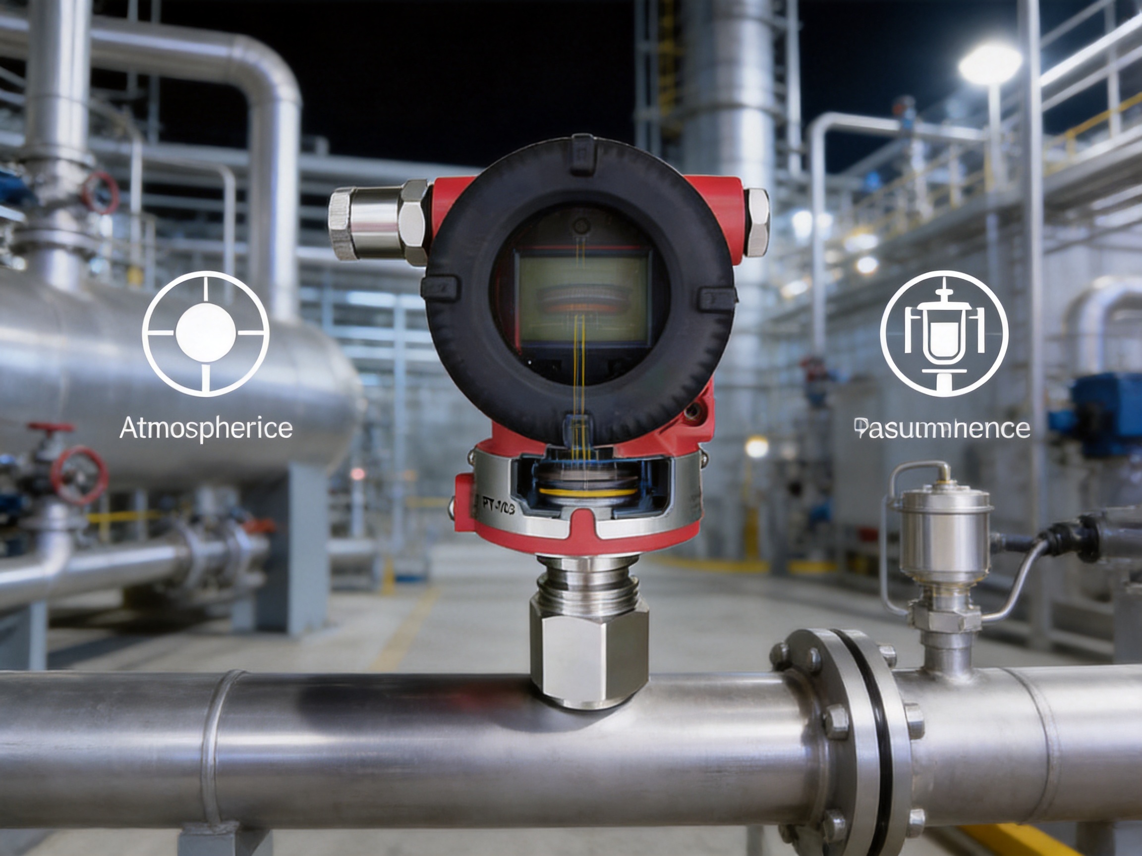
The transmitter is available in gauge-pressure and absolute-pressure versions. Gauge pressure is referenced to local atmospheric pressure and is commonly used for ordinary pipelines, tanks, pumps, compressors, and process vessels. Absolute pressure is referenced to a perfect vacuum and is more suitable for vacuum systems, distillation service, evaporation, low-pressure processes, and applications in which atmospheric pressure variation must not influence the reading.
With broad application coverage, multiple diaphragm and fill-fluid choices, adjustable ranges, optional explosion-proof treatments, local calibration capability, and robust materials, the XG3051T is positioned as a versatile solution for industrial pressure measurement.
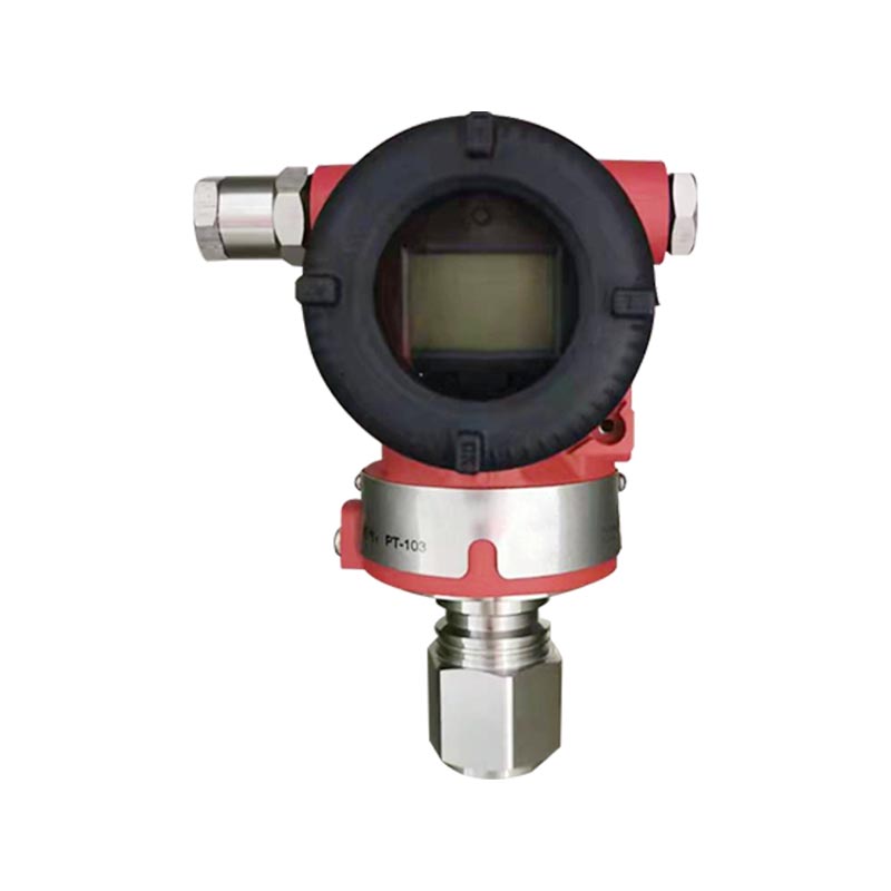
XG3051T Differential pressure/absolute pressure transmitter
The most distinctive feature of the XG3051T is its direct-connected structure. The transmitter is installed directly on the process pipeline, vessel, or compatible process adapter. This arrangement can simplify the overall pressure measurement system because it reduces dependence on long impulse lines and external pressure accessories.
In a traditional remote pressure measurement installation, the process pressure must travel through a tube before reaching the transmitter. The tube may become blocked by solids, viscous liquids, crystallized materials, condensation, or corrosion products. Temperature differences can also cause the measured medium to change state inside the impulse line. In severe climates, the line may freeze or require heat tracing. The direct-connected architecture minimizes these concerns and helps the measured pressure reach the sensing element with fewer intermediate influences.
Direct installation can also reduce response delay. Although the transmitter has configurable damping for process stability, a shorter pressure path generally helps the instrument respond more directly to process changes. This is valuable in pressure control loops, pump protection, compressor monitoring, and fast-changing production processes.
The XG3051T uses a capacitive sensing structure to detect pressure. When process pressure acts on the diaphragm, the sensing element undergoes a very small mechanical displacement. This displacement changes the capacitance within the sensor. Internal electronics convert the capacitance change into a stable electrical output corresponding to the applied pressure.
Capacitive sensing provides several advantages for industrial service. The sensing mechanism can offer good repeatability, high sensitivity, and strong resistance to mechanical wear because it does not depend on sliding electrical contacts. The sensor can also be configured for a wide range of pressure spans, allowing one transmitter platform to cover low-pressure, medium-pressure, high-pressure, and absolute-pressure applications.
The process diaphragm is manufactured from 316L stainless steel as the standard option. Hastelloy C is also available for applications requiring greater resistance to selected corrosive media. The appropriate diaphragm material should always be selected according to the actual process composition, concentration, temperature, pressure, and cleaning method.
Gauge-pressure measurement compares process pressure with the atmospheric pressure surrounding the transmitter. If atmospheric pressure changes, the gauge-pressure reference changes accordingly. This is normally desirable when the purpose of measurement is to determine how much pressure exists above or below the local atmosphere.
Typical gauge-pressure applications include monitoring a water pipeline, measuring pump discharge pressure, checking compressed-air pressure, monitoring tank pressure, and controlling steam or gas distribution systems. The gauge-pressure models cover ranges from low-pressure measurement up to high-pressure service, including ranges reaching tens of megapascals.
Absolute-pressure measurement compares the process pressure with an absolute vacuum reference. It is not affected by normal changes in atmospheric pressure. Absolute pressure is therefore important in vacuum systems, distillation columns, vacuum drying, evaporation equipment, vacuum packaging, and processes where boiling-point or vapor-pressure calculations depend on an accurate absolute reference.
The gauge-pressure and absolute-pressure versions use different sensing references and should not be considered directly interchangeable. Selection must be made before ordering and should be based on the process measurement principle rather than only on the desired numerical range.
A major advantage of the XG3051T is its range flexibility. Gauge-pressure range codes cover low-pressure measurement from approximately 0.6 kPa full range, medium-pressure measurement, and high-pressure measurement up to 60 MPa depending on the selected model. Absolute-pressure versions cover ranges from low absolute pressure through approximately 3 MPa.
The measurement span can be adjusted within the upper and lower limits of the selected range. This allows the same basic transmitter design to be configured for different operating requirements. The recommended practice is to select the range code that provides the lowest practical turndown ratio while still covering the process pressure. Operating closer to the optimized range generally supports better performance characteristics and reduces unnecessary loss of resolution.
Low-pressure versions are suitable for air ducts, ventilation systems, water columns, clean gas systems, and low-pressure process monitoring. Medium-pressure versions can be used for water treatment, general industrial pipelines, hydraulic systems, and utility services. High-pressure models are available for hydraulic machinery, high-pressure water systems, oil and gas facilities, and other demanding applications.
The reference accuracy for the standard adjustment range is specified as ±0.075 percent, including zero-based linearity, hysteresis, and repeatability. Depending on the selected configuration, product information also provides alternative accuracy options. This allows users to balance measurement performance and project cost according to the needs of the control system.
For applications with a turndown ratio greater than 10, the stated accuracy may be influenced by the selected adjusted span. The applicable performance relationship is expressed as ±(0.0075 × TD) percent under the stated conditions. Proper range selection is therefore important. A transmitter should not be selected solely by its maximum pressure capability if the actual operating span is very small in comparison.
Long-term stability is another important consideration. For the B/L range codes, the stated long-term drift is up to ±0.2 percent of span per year. For other range codes, the stated drift is up to ±0.1 percent of span per year. These characteristics help reduce the frequency of manual recalibration and support predictable maintenance planning.
The standard intelligent configuration provides a two-wire 4–20 mA output with HART digital communication. The analog signal is widely accepted by industrial control systems and can be transmitted over long cable distances when the power supply and loop resistance are correctly designed. The HART layer adds digital access to configuration parameters, measurement information, diagnostic data, range settings, damping values, and calibration functions without replacing the familiar analog signal.
The transmitter can also be configured with a 4–20 mA analog output option without digital communication when a simple analog loop is preferred. For modern process automation projects, however, the 4–20 mA plus HART configuration provides greater flexibility. It allows operators and maintenance technicians to obtain detailed information through a HART communicator or compatible control-system interface while retaining compatibility with existing analog input cards.
The digital communication load range is specified as approximately 230 to 600 ohms. The power supply is normally 24 VDC, with an allowable supply range extending up to 42 VDC under the stated loop conditions. Loop design should account for cable resistance, control-system input resistance, safety barriers, surge protection, and any additional devices installed in series.
The output can be configured as linear or square-root. Linear output is the normal choice when the transmitter is measuring pressure directly. Square-root output is useful when pressure is used to infer flow through a primary flow element such as an orifice plate or other differential-pressure-based device, provided that the complete measurement arrangement is designed for this purpose.
This selectable output function allows the transmitter to serve more than one role in an instrumentation system. It can be used for direct pipeline pressure measurement or integrated into an application where the pressure signal is mathematically related to flow. Proper engineering configuration is necessary because square-root extraction should only be used when it corresponds to the actual process measurement principle.
The XG3051T can be supplied without a display or with a local LCD or OLED display. A local display allows personnel to view the measured pressure near the process connection without opening a control-room interface. This is useful during commissioning, routine inspection, troubleshooting, and field calibration.
Local or manual calibration functions allow authorized technicians to adjust zero and span according to the specified measurement range. HART communication provides an additional method for configuration and calibration. These functions help maintenance teams perform field service efficiently, particularly in installations where the transmitter is located far from the main control room.
The display options have different temperature limitations. The LCD option is specified for ambient conditions down to approximately −20 °C, while the OLED option is available for lower-temperature service down to approximately −40 °C under the stated product configuration. Users should select the display type according to the actual environmental conditions.
The transmitter housing is designed for industrial outdoor and indoor installation. The supplied specifications identify an enclosure protection rating of IP67, while other product descriptions refer to IP65 protection. The exact rating should be confirmed against the final ordered configuration and certification documentation. In either case, correct cable-gland installation, cover sealing, grounding, and maintenance are essential to preserve the intended enclosure protection.
The normal ambient temperature range is approximately −40 to 85 °C, with a more limited range when certain LCD and FKM sealing configurations are selected. Storage and transport temperatures may extend from approximately −50 to 85 °C, again subject to display configuration. The transmitter should not be installed where the environmental temperature or process temperature exceeds the approved range.
The aluminum-alloy housing is coated with epoxy resin to improve resistance to common industrial environments. A full stainless-steel housing is also available as an additional option for projects requiring enhanced mechanical or environmental durability.
The following table summarizes selected technical characteristics. Final values depend on the chosen pressure range, output, diaphragm material, process connection, display, sealing materials, and special options.
| Item | Typical Specification or Option | Application Significance |
|---|---|---|
| Measurement type | Gauge pressure or absolute pressure | Supports ordinary pressure and vacuum-related applications |
| Sensor principle | Capacitive sensing | Provides sensitive, repeatable pressure detection |
| Standard diaphragm | 316L stainless steel | Suitable for many industrial gases, liquids, and vapors |
| Optional diaphragm | Hastelloy C | For selected corrosive-service requirements |
| Output | Two-wire 4–20 mA; optional HART | Compatible with common industrial control systems |
| Power supply | Typically 24 VDC; maximum approximately 42 VDC | Suitable for standard industrial loop power systems |
| Reference accuracy | Up to ±0.075 percent under specified conditions | Supports process monitoring and control |
| Warm-up time | Less than approximately 15 seconds | Enables relatively rapid commissioning |
| Amplifier damping | Approximately 0.1 seconds | Provides fast basic signal response |
| Additional damping | Adjustable from approximately 0.1 to 60 seconds | Helps stabilize noisy process signals |
| Process connection | Standard 1/2-inch NPT internal thread; adapters available | Supports multiple piping and equipment interfaces |
| Housing material | Epoxy-coated aluminum alloy; stainless option available | Provides practical mechanical and environmental protection |
| Protection rating | IP65 or IP67 depending on documentation and configuration | Suitable for many field installations when correctly assembled |
The gauge-pressure range family includes codes B, C, D, F, G, H, I, and J. The low-pressure B range covers approximately 0.6 to 6 kPa, with a span that can extend from negative pressure to positive pressure within the specified limits. This range is appropriate for low-pressure gas, ventilation, air-handling, and water-column applications.
The C range covers approximately 2 to 40 kPa, and the D range covers approximately 2.5 to 250 kPa. These ranges can be used for low- and medium-pressure process pipelines, tank pressure, pump systems, and utility services. The F range covers approximately 30 to 3000 kPa, or up to 3 MPa, making it suitable for many general industrial and hydraulic applications.
Higher ranges include G, H, I, and J. Depending on the selected code, the upper measurement limit extends to approximately 10, 21, 40, or 60 MPa. These versions support demanding applications such as high-pressure water systems, hydraulic equipment, oil and gas pipeline networks, and industrial machinery.
Absolute-pressure versions include low- and medium-pressure ranges identified by codes L, M, and O in the detailed performance information. The L range covers approximately 2 to 40 kPa, the M range covers approximately 2.5 to 250 kPa, and the O range covers approximately 30 to 3000 kPa. The adjustable span begins at absolute vacuum reference and extends within the selected range.
Absolute-pressure models are especially useful where atmospheric-pressure variation could create measurement error. For example, in a vacuum vessel, a gauge-pressure reading may change when barometric pressure changes even if the vacuum condition inside the vessel remains constant relative to absolute pressure. An absolute-pressure transmitter avoids this ambiguity.
The transmitter includes overload limits according to the selected range. Low-range models have defined overload capability, while higher-pressure versions provide overload limits reaching tens of megapascals. The applicable overload value must be checked against the exact model code before installation.
Overload protection helps the instrument withstand temporary pressure excursions, but it should not be interpreted as permission to operate continuously beyond the rated measurement range. Repeated or severe overpressure can affect sensor stability, diaphragm integrity, calibration, or process seals. Pressure relief devices and appropriate process protection should be used where pressure spikes are possible.
The standard process connection is a 1/2-inch NPT internal thread. Optional configurations include a 1/2-inch NPT external thread with an internal 1/4-inch NPT passage, an M20 × 1.5 external thread, a G1/2 external thread, a 1/4-inch NPT external thread, and a KF16 vacuum connection conforming to the listed vacuum-interface standards.
The KF16 vacuum connection is intended for suitable low-pressure and vacuum applications and is limited to the specified pressure range. The connection type should be selected according to the process equipment, sealing method, national or international piping practice, and maintenance requirements at the installation site.
Correct thread engagement, sealing material, tightening torque, and alignment are important. Improper installation can damage the process port, create leakage, introduce mechanical stress, or cause a zero shift. The transmitter should never be used as a structural support for unsupported pipework.
The standard sensing diaphragm is 316L stainless steel with silicone oil as the filling fluid. An alternative 316L and fluorinated-oil configuration is available, as are Hastelloy C diaphragm versions with either silicone oil or fluorinated oil.
Material selection depends on the medium and the application. 316L stainless steel is suitable for many clean gases, liquids, and vapors. Hastelloy C may provide improved resistance in selected corrosive environments, but its suitability must be evaluated using detailed chemical compatibility data. For oxygen measurement, the oil-free treatment option uses fluorinated oil, an FKM sealing ring, and specified limits such as pressure below 6 MPa and temperature below 60 °C.
Strongly corrosive, abrasive, highly viscous, crystallizing, or contaminated media require a detailed review before selection. The process medium must not attack the diaphragm, process connection, seals, or internal wetted surfaces. If necessary, protective separators, flushing systems, remote seals, or specialized materials should be considered.
In petrochemical and chemical plants, pressure measurement supports reaction control, distillation, storage, transfer, separation, and utility management. The absolute-pressure version is suitable for vacuum distillation and other low-pressure operations where the vacuum reference is important. Gauge-pressure versions can monitor pumps, compressors, pipelines, vessels, and utility headers.
The stainless-steel diaphragm and optional Hastelloy C configuration provide material choices for different process environments. Explosion-proof treatments can be selected for hazardous areas, subject to the applicable certification, installation method, barrier requirements, and site classification.
Power plants use pressure transmitters in feedwater systems, cooling-water networks, fuel systems, steam-related equipment, compressed-air systems, and auxiliary services. The transmitter’s 4–20 mA output can be connected to plant control systems, while HART communication assists maintenance and calibration teams.
In power-generation environments, temperature, vibration, electromagnetic interference, and pressure transients must be considered. The transmitter’s configurable damping can help reduce unstable readings caused by pulsating pumps or turbulent flow. The installation should still include appropriate snubbers, pulsation dampers, or process protection where required.
Water treatment plants require pressure measurement for raw-water intake, filtration, dosing, pumping, distribution, and wastewater handling. Direct-connected installation can simplify pressure monitoring at pump discharge points, pipelines, and treatment equipment. The broad low- and medium-pressure range coverage supports many municipal and industrial water systems.
For water containing suspended solids, biological material, or chemicals, the process connection should be installed where blockage risk is minimized. Regular inspection is recommended in applications where deposits or scaling could cover the diaphragm or restrict the pressure port.
Pipeline operators monitor pressure to identify pump performance, flow restrictions, valve conditions, and abnormal operating states. Gauge-pressure models are commonly selected for pipeline pressure, while absolute-pressure models may be used in specialized low-pressure or vacuum-related systems.
High-pressure range options, adjustable damping, HART communication, and explosion-proof selections make the transmitter suitable for many pipeline instrumentation projects. Final selection must consider the pipeline medium, pressure rating, hazardous-area classification, ambient temperature, vibration, and required certification.
Metallurgical plants often contain high temperatures, dust, vibration, hydraulic systems, cooling-water circuits, gas networks, and corrosive process substances. The transmitter can be used for hydraulic pressure, gas pressure, water pressure, and auxiliary process monitoring when installed within its environmental and process limits.
In areas with severe vibration or high radiant heat, the transmitter should be mounted in a protected location or connected through an appropriate pressure-management arrangement. The stated environmental limits apply to the transmitter body and electronics; the process connection must also be protected from excessive process temperature.
Packaged systems and process skids benefit from compact instruments that are easy to configure and integrate. The direct-connected design can reduce the size of the pressure measurement assembly. M20 × 1.5, G1/2, NPT, and vacuum connection options support different equipment designs and export-market requirements.
Local displays are useful on packaged equipment because commissioning technicians can verify pressure without connecting a separate handheld instrument. HART communication provides additional access when the skid is integrated into a larger automation system.
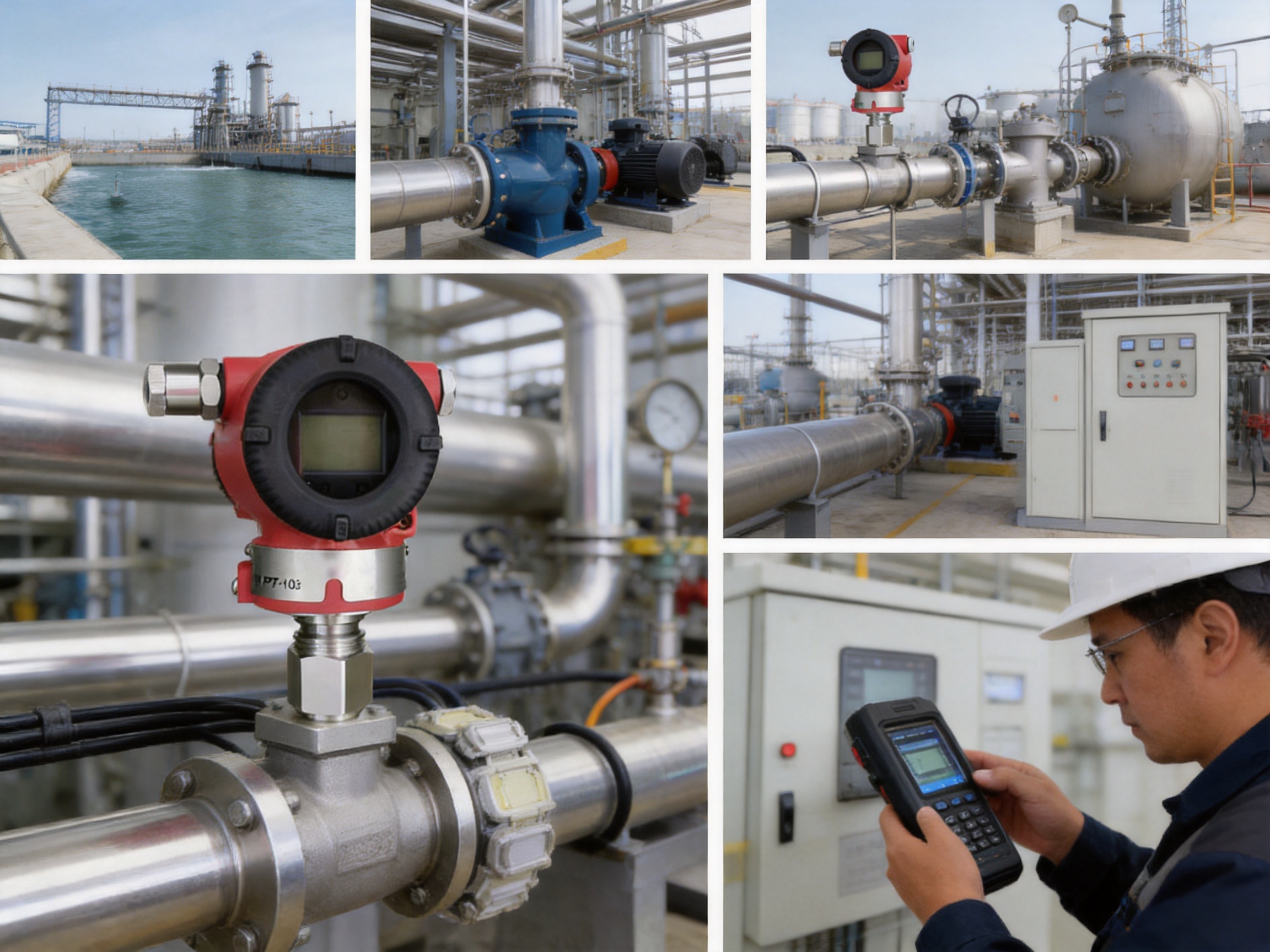
Compared with a transmitter installed through long impulse tubing, the direct-connected design can reduce the number of accessories required. Fewer components may mean fewer potential leak points, lower installation labor, less support hardware, and easier inspection. This is especially valuable on compact skids, remote pipeline stations, and equipment where space is limited.
Some pressure transmitters are optimized for only a narrow pressure range or a single output protocol. The XG3051T offers a broader configuration structure, including gauge and absolute pressure, multiple range codes, several process connections, different diaphragm materials, multiple display choices, and explosion-proof treatments.
This adaptability can simplify standardization across a plant. Instead of maintaining many unrelated transmitter platforms, an engineering department may be able to use one product family for low-pressure, medium-pressure, high-pressure, gauge, absolute, hazardous-area, and local-display requirements.
HART communication and optional local displays help maintenance technicians access operating information at the instrument. Zero and span can be adjusted within the permitted measurement range, and damping and output functions can be configured according to process requirements.
Maintenance personnel should follow site authorization procedures and calibration standards. Digital access does not replace a formal calibration program, but it can reduce troubleshooting time and help identify incorrect range settings, power-supply problems, wiring faults, or abnormal process conditions.
The XG3051T combines industrial materials, intelligent communication, flexible configuration, and a practical direct-connected structure. This balance can provide a lower total cost of ownership than an installation that requires a more complicated pressure accessory system or multiple specialized transmitter families.
Total cost should be evaluated over the entire equipment life cycle. Important factors include purchase cost, process accessories, installation labor, commissioning time, calibration effort, spare-parts inventory, downtime risk, energy consumption, and replacement requirements. A transmitter with appropriate range selection and robust material compatibility can deliver more value than a lower-priced instrument that requires frequent maintenance or early replacement.
The manufacturer behind the XG3051T is part of an industrial group established in 1997 in Anhui, China. The group includes companies involved in instrumentation, alloy materials, cables, and precious metals. This broader manufacturing structure supports a combination of product development, material knowledge, machining, assembly, testing, and industrial supply-chain management.
The group operates from a modern industrial base with a reported land area of more than 150 mu and a construction area of approximately 60,000 square meters. Its workforce includes nearly 300 employees, including professional technicians, senior technical experts, engineers, and assistant engineers. This technical workforce supports product design, process improvement, quality control, application assistance, and customization.
Reliable pressure transmitters require controlled manufacturing at every stage. The production process begins with material selection and incoming inspection. Stainless-steel diaphragms, process connections, housing components, sealing rings, electronic components, and filling materials must meet defined requirements before entering production.
Precision machining is used to manufacture process connections, threaded interfaces, sensor-related parts, and housing components. Dimensional control is important because thread accuracy, diaphragm positioning, sealing surfaces, and internal clearances influence both mechanical reliability and measurement performance.
Diaphragm assembly and filling are particularly important steps. The sensing diaphragm must be installed without damage, contamination, distortion, or excessive residual stress. Filling-fluid handling must be controlled to reduce the possibility of air bubbles or contamination affecting measurement stability. Sealing operations must be verified to protect the sensor and electronics from process leakage and environmental ingress.
Electronic assembly includes the sensor interface, signal-conditioning circuitry, analog output stage, communication functions, display interface, and protection components. Calibration is then performed using controlled pressure sources and reference instruments. The calibration process establishes the relationship between applied pressure and output signal over the selected range.
Quality assurance is not limited to final visual inspection. A professional transmitter manufacturing process includes incoming-material inspection, in-process checks, dimensional verification, electrical testing, pressure testing, calibration, output verification, communication testing, and final inspection.
Testing may include zero and span verification, linearity checks, repeatability checks, hysteresis evaluation, overload assessment, insulation and wiring inspection, display operation, HART communication, enclosure sealing, and temperature-related performance assessment. The exact inspection plan depends on the configuration and applicable project requirements.
Electromagnetic compatibility testing is also important for instruments used in industrial environments. The listed EMC schedule includes radiated emission, conducted emission, electrostatic discharge immunity, radio-frequency electromagnetic-field immunity, power-frequency magnetic-field immunity, electrical fast transient immunity, surge immunity, and conducted RF disturbance immunity.
Performance levels in the EMC schedule distinguish normal operation from temporary degradation with self-recovery. This provides useful information for system designers when evaluating the transmitter alongside control-system equipment, cable routing, grounding, surge protection, and hazardous-area barriers.
The group reports certification for ISO 9001 quality management, ISO 14001 environmental management, and GB/T 28001 occupational health and safety management. These systems support structured control of manufacturing processes, environmental responsibilities, workplace safety, documentation, corrective actions, and continuous improvement.
Management certification does not replace product-specific technical evaluation, but it demonstrates that the organization has established formal systems for managing quality and operational performance. For international buyers, such systems can support supplier qualification and project documentation.
The group maintains research and development capabilities supported by engineers and technical specialists. Its product portfolio spans temperature instruments, pressure instruments, flow meters, level instruments, alloy wire, cables, precious-metal materials, and related industrial accessories.
This broad portfolio is advantageous when customers require multiple instrumentation categories from one supplier. It can also support technical coordination across pressure, temperature, flow, level, and material-selection requirements. Where standard configurations are not sufficient, customers can discuss process connections, diaphragm materials, output options, displays, housing choices, cable entries, and hazardous-area requirements with the manufacturer.
Before selecting the transmitter, users should document the medium, normal pressure, maximum pressure, minimum pressure, operating temperature, ambient temperature, pressure pulsation, vibration, corrosiveness, hazardous-area classification, required accuracy, output protocol, process connection, and display requirement.
The measurement reference must also be established. If the process requires pressure relative to atmosphere, choose a gauge-pressure model. If the measurement must remain independent of atmospheric changes or involves a vacuum reference, choose an absolute-pressure model. The two types should not be substituted without technical confirmation.
The transmitter should be mounted in a location that is accessible for inspection and calibration but protected from direct impact, excessive vibration, extreme radiant heat, flooding, and corrosive external contamination. The process connection must be compatible with the pipeline or equipment thread and sealing method.
When measuring liquids, the installation should avoid locations where gas pockets can form. When measuring gases, the installation should avoid locations where liquid condensate can collect in the pressure port. For steam or hot vapor service, suitable cooling, condensate management, or remote installation methods may be necessary to keep the transmitter within its process-temperature limits.
The transmitter uses terminals suitable for approximately 0.5 to 2.5 square millimeter conductors, with an M20 × 1.5 cable gland arrangement identified in the specifications. Wiring should be performed by qualified personnel using the correct polarity, cable type, grounding method, and hazardous-area practices.
The power supply and loop resistance must satisfy the relationship between supply voltage, minimum operating voltage, and maximum loop current. For HART communication, the loop must provide a suitable resistance, generally within the stated 230 to 600 ohm range. Excessive cable resistance or inadequate supply voltage may prevent correct operation or communication.
During commissioning, verify the model, range code, process connection, diaphragm material, output type, display option, and explosion-proof treatment against the purchase specification. Confirm that the pressure port is open to the process and free from blockage. Check all electrical connections, cable glands, covers, grounding points, and sealing components.
Apply a known pressure where possible and compare the local display, analog output, and digital reading. Confirm the configured lower and upper range values, alarm behavior, damping, linear or square-root output selection, engineering units, and direction of response. Any zero adjustment should be carried out only when the transmitter is at the correct reference pressure.
Routine maintenance should include visual inspection, leakage checks, cable-gland inspection, housing and cover inspection, process-port cleaning where appropriate, signal verification, and periodic calibration. The maintenance interval depends on process criticality, regulatory requirements, environmental conditions, measurement stability, and the consequences of measurement error.
If the output is missing or unstable, first verify the 24 VDC supply and loop polarity. Check for loose terminals, damaged cables, insufficient loop resistance, incorrect barriers, or an open circuit. If the output is present but incorrect, check the configured range, engineering units, zero point, process isolation valves, pressure port, and actual process condition.
Numerical jumps may result from electrical interference, unstable power, mechanical vibration, pressure pulsation, blocked passages, gas bubbles, liquid condensation, or incorrect damping. HART communication can help review diagnostic information and configuration settings. If the transmitter has been exposed to overload, impact, excessive temperature, or corrosive media, calibration and sensor integrity should be evaluated.
A failed output does not always indicate an electronic failure. Process blockage, incorrect installation orientation, a closed isolation valve, a faulty power supply, or wiring errors are common causes. Troubleshooting should proceed from the simplest external causes to sensor and electronics inspection.
Explosion-proof and intrinsically safe versions are available, including listed intrinsic-safety and flameproof treatments. The selected certification must match the hazardous-area classification, gas or dust group, temperature class, installation method, cable entry, barrier or isolator requirements, and local regulations.
A flameproof configuration may require a compatible flameproof cable entry device. An intrinsically safe configuration may require an approved associated apparatus and correctly calculated entity parameters. Users must follow the certification documentation and installation instructions supplied with the exact product configuration.
Pressure systems can be hazardous even when the electrical installation is safe. Before removing the transmitter, isolate and depressurize the process. Confirm that the medium is not toxic, flammable, corrosive, hot, or otherwise dangerous. Personal protective equipment and site-specific permit procedures must be used.
| Selection Question | Recommended Review |
|---|---|
| What pressure reference is required? | Select gauge pressure for atmospheric reference or absolute pressure for vacuum reference. |
| What is the normal and maximum pressure? | Choose a range code that covers the process while avoiding unnecessary turndown. |
| What is the minimum operating pressure? | Confirm that the adjusted span remains above the applicable minimum span. |
| What is the process medium? | Check compatibility with the diaphragm, connection, fill fluid, and seals. |
| Is the medium corrosive? | Consider Hastelloy C or another approved material after technical review. |
| Is oxygen service involved? | Select the oil-free treatment and observe the specified pressure and temperature limits. |
| Is HART communication required? | Choose the 4–20 mA plus HART configuration and provide suitable loop resistance. |
| Is local indication necessary? | Select no display, LCD, or OLED according to temperature and visibility needs. |
| Is the site hazardous? | Choose the applicable intrinsic-safety or flameproof treatment and cable entry. |
| Which process connection is needed? | Select NPT, M20, G1/2, KF16, or another compatible configuration. |
| Are vibration or pulsation present? | Review mounting, pressure protection, damping, and possible pulsation control. |
| What documentation is required? | Confirm calibration certificates, material information, certification, and inspection records. |
The value of a pressure transmitter depends on more than nominal accuracy. A practical instrument must be easy to specify, install, configure, integrate, maintain, and replace. The XG3051T addresses these requirements through a combination of direct-connected installation, flexible pressure references, broad ranges, common industrial outputs, HART communication, local display options, material choices, and protection treatments.
Its direct-connected design can reduce the complexity associated with impulse tubing and external accessories. Its capacitive sensing technology provides a robust measurement foundation. Its 4–20 mA output supports established control architectures, while HART communication adds digital configuration and diagnostic capability. Its adjustable damping helps adapt the signal to stable or dynamic process conditions.
The range structure supports applications from low-pressure air and water measurement to high-pressure industrial service. Gauge and absolute versions address different measurement principles without forcing users to adopt separate unrelated product families. Process connections and material options provide additional flexibility for domestic and international equipment designs.
The manufacturing organization adds value through its experience in industrial instrumentation, alloy materials, cable products, and related components. Its reported quality, environmental, and occupational-safety management systems, together with research and development resources and structured inspection procedures, support consistent production and long-term supplier cooperation.
For customers seeking a dependable pressure measurement platform, the XG3051T offers a well-balanced combination of measurement performance, field adaptability, integration capability, and manufacturing support. Correct model selection remains essential, but the platform provides a strong starting point for industrial pressure monitoring and control projects.
Gauge pressure is referenced to local atmospheric pressure, while absolute pressure is referenced to an absolute vacuum. Gauge pressure is normally used for ordinary pipelines, tanks, pumps, and process equipment. Absolute pressure is preferred for vacuum systems, distillation, evaporation, and applications where atmospheric-pressure variation must not affect the measurement. The two versions use different pressure references and should not be directly interchanged.
Yes. The intelligent configuration provides a two-wire 4–20 mA output with HART digital communication. HART can be used for parameter configuration, range adjustment, diagnostics, digital pressure reading, and calibration support. A 4–20 mA analog-only option is also available for systems that do not require digital communication.
Yes. The direct-connected structure allows the process medium to act directly on the sensing diaphragm through the process connection. The standard diaphragm material is 316L stainless steel. Hastelloy C options are available for selected corrosive applications. The material must be confirmed against the complete process composition and operating conditions before ordering.
The oil-free treatment option is intended for oxygen measurement and uses fluorinated oil filling, an FKM sealing ring, and specified limitations, including pressure below approximately 6 MPa and temperature below approximately 60 °C. Oxygen-service cleanliness and installation procedures must be followed carefully.
Common causes include an unstable 24 VDC supply, loose wiring, incorrect polarity, an unsuitable loop resistance, a blocked process port, closed isolation valves, pressure pulsation, vibration, electromagnetic interference, incorrect range settings, or a zero-point error. Check the power and wiring first, then inspect the process connection and configuration. HART communication can assist with parameter verification.
Explosion-proof selections are available, including intrinsic-safety and flameproof treatments. The exact version must match the area classification, certification requirements, associated electrical equipment, and cable-entry method. Installation must be performed according to the applicable certification documentation and local regulations.
The transmitter is normally powered by 24 VDC. The allowable supply can extend up to approximately 42 VDC, subject to the specified loop conditions. The available voltage at the transmitter must be sufficient after accounting for cable resistance, control-system input resistance, barriers, and other series devices.
The output can be selected as linear or square-root. Square-root output may be used when the transmitter signal is derived from a differential-pressure flow measurement arrangement. It should not be selected for ordinary direct pressure measurement unless the square-root relationship is appropriate to the application.
The standard process connection is a 1/2-inch NPT internal thread. Options include 1/2-inch NPT external thread with internal 1/4-inch NPT, M20 × 1.5 external thread, G1/2 external thread, 1/4-inch NPT external thread, and a KF16 vacuum connection for suitable low-pressure applications.
Yes. The transmitter can be supplied without a display, with an LCD display with backlight, or with an OLED display. Display temperature limits differ, so the selection should reflect the ambient temperature at the installation site.
The range should cover the normal operating pressure and all expected process conditions without creating an unnecessarily high turndown ratio. The product documentation recommends selecting the range code with the lowest practical turndown ratio to optimize performance. The calibrated span must also satisfy the stated minimum-span requirement.
Confirm the pressure reference, range code, process medium, maximum pressure, process and ambient temperatures, diaphragm material, fill fluid, process connection, output protocol, display, hazardous-area treatment, cable entry, and required documentation. Also verify that the installation location is protected from excessive vibration, impact, heat, flooding, and corrosive contamination.
The XG3051T is a flexible industrial pressure transmitter for gauge-pressure and absolute-pressure measurement. Its direct-connected structure simplifies many installations, while capacitive sensing, 316L stainless steel construction, optional Hastelloy C diaphragms, 4–20 mA output, HART communication, adjustable damping, local display options, and broad pressure-range coverage support diverse process requirements.
Its applications extend across petrochemical, chemical, power, metallurgy, water treatment, oil and gas, utilities, packaged equipment, and general industrial automation. Compared with more complicated pressure measurement arrangements, the transmitter can reduce accessory requirements, shorten the pressure path, simplify maintenance, and support more compact installations.
Behind the product is an industrial manufacturing organization with experience in instrumentation, alloy materials, cables, and related products. Its engineering staff, modern production facilities, quality-management systems, testing procedures, and research capabilities provide a foundation for dependable supply and technical support.
When the pressure reference, range, material compatibility, process connection, environmental conditions, and certification requirements are correctly evaluated, the XG3051T can provide accurate, stable, and maintainable pressure information for modern industrial control systems.
1. Industrial Pressure Measurement Principles, guidance on gauge-pressure, absolute-pressure, sensor selection, and calibration practices.
2. Process Instrumentation Engineering Handbook, recommendations for pressure transmitter installation, impulse-line management, damping, and commissioning.
3. ISO 9001 Quality Management Systems, principles for controlled manufacturing, inspection, corrective action, and continuous improvement.
4. ISO 14001 Environmental Management Systems, framework for environmental responsibilities in industrial production.
5. GB/T 28001 Occupational Health and Safety Management Systems, guidance for workplace safety management.
6. Electromagnetic Compatibility Test Standards, including radiated emission, conducted emission, electrostatic discharge, surge, burst, and radio-frequency immunity testing.
7. Industrial Process Control and Automation Practices, recommendations for 4–20 mA loops, HART communication, grounding, shielding, and control-system integration.
8. Pressure Equipment Installation and Maintenance Guidelines, covering process isolation, overpressure protection, material compatibility, hazardous-area installation, and field calibration.



 INQUIRY
 English
 عربى
 русский
 中文简体