
Reliable process measurement is essential for safe, efficient, and stable industrial production. In petrochemical plants, power stations, water-treatment facilities, metallurgical operations, and paper mills, differential pressure information is frequently used to monitor flow, liquid level, filtration performance, furnace draft, and pressure balance across process equipment. The XG3051DP Differential Pressure Transmitter is designed for these demanding duties. It converts the differential pressure of a measured medium into a standardized 4–20 mA signal, with optional HART digital communication for configuration, diagnostics, and commissioning.
Based on a capacitive sensing principle, the XG3051DP combines a pressure-sensitive measuring capsule, intelligent electronic processing, adjustable measurement ranges, flexible materials, and a broad selection of process and installation options. Its design allows one instrument platform to serve many applications, from low differential pressure measurement in ventilation and filtration systems to higher-pressure process control in industrial pipelines and vessels.
The transmitter is not limited to measuring differential pressure as an isolated process variable. With appropriate installation and configuration, it can measure pipeline flow, the level of liquids in closed containers, filter pressure loss, furnace negative pressure, and other parameters derived from pressure difference. When used for flow measurement, the square-root function can be activated so that the output signal corresponds more closely to the actual flow relationship.
Manufactured by Xinguo Group Co., Ltd., the instrument benefits from the company’s experience in temperature instruments, pressure instruments, flow meters, level instruments, alloy materials, cables, and industrial accessories. The group combines product development, materials expertise, production facilities, inspection procedures, and quality management systems to provide instrumentation for international industrial users.
For users seeking a practical alternative to higher-cost imported transmitters, the XG3051DP offers a combination of intelligent communication, broad configuration capability, competitive accuracy, multiple diaphragm materials, high protection, and adaptable installation. Its specification range supports both general industrial service and specialized applications where corrosion resistance, oxygen service, explosion-proof treatment, or severe process conditions must be considered.
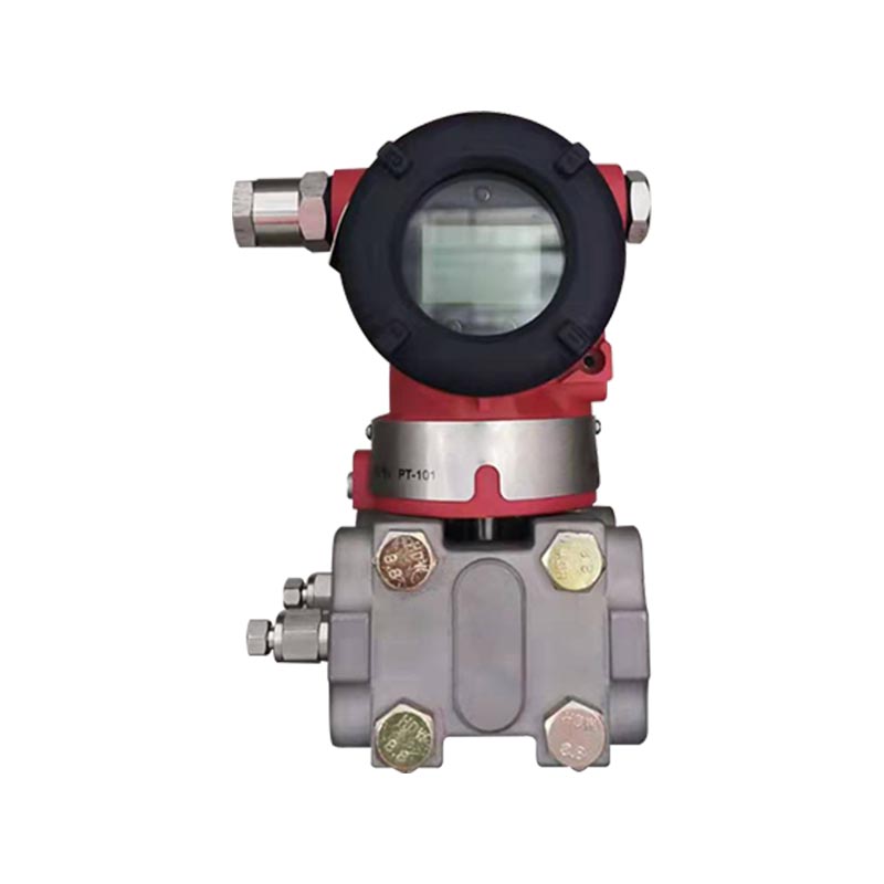
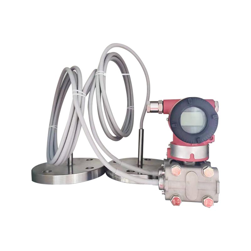
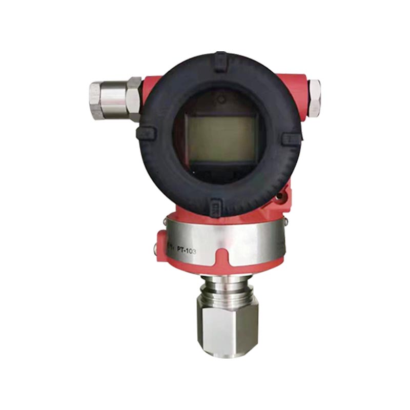
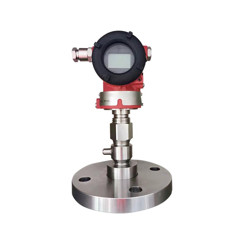
XG3051DP Differential pressure transmitter
The XG3051DP measures the difference between pressure applied to its high-pressure and low-pressure sides. The two pressure inputs act on a capacitive sensing element through isolating diaphragms and a fill fluid. A change in differential pressure causes a minute displacement or change in the sensing structure. The electronic unit detects this change, applies compensation and signal processing, and produces a proportional output.
The standard output is a two-wire 4–20 mA DC signal. A 4 mA output represents the configured lower range value, while a 20 mA output represents the configured upper range value. HART communication may be included to provide digital access to the measurement value, range settings, damping, alarm configuration, square-root operation, and calibration functions. This combination of analog transmission and digital communication makes the transmitter suitable for DCS, PLC, and other process-control systems.
The transmitter can be configured for linear output or square-root output. Linear output is normally selected when the required process variable is differential pressure. Square-root output is useful for differential-pressure flow measurement because flow is related approximately to the square root of differential pressure across a primary device such as an orifice plate, nozzle, or other restriction.
Although the XG3051DP can support several derived measurement applications, it is fundamentally a differential pressure transmitter. It does not directly measure absolute pressure. When used for level measurement in a closed vessel, the high- and low-pressure connections must be arranged according to the vessel configuration and the density, temperature, and vapor conditions of the process medium. Correct impulse piping and proper calibration are essential for accurate results.
A major advantage of the XG3051DP is its ability to support several measurement duties through one differential-pressure architecture. The same basic instrument can be applied to flow monitoring, closed-tank level measurement, filter differential pressure, pipeline pressure difference, boiler draft, and other process applications. This reduces the need for multiple unrelated transmitter designs and simplifies spare-parts planning.
Users can select an appropriate range code and configure the calibrated range within the upper and lower limits of that code. This flexibility helps accommodate different process requirements while retaining a common instrument family. For plants with numerous measurement points, standardizing on one transmitter platform can reduce training requirements and make maintenance procedures more consistent.
The combination of a conventional 4–20 mA signal and optional HART communication provides compatibility with established control systems while allowing access to digital configuration and diagnostic information. Plants that continue to use analog input cards can connect the transmitter in the usual two-wire loop. Plants with HART-capable systems or handheld communicators can use the digital channel to adjust settings, verify the measurement, and support commissioning without removing the device from service.
HART communication requires a loop resistance within the specified communication range, normally including a 250-ohm resistor in series with the circuit. The transmitter supports a digital communication load range of 250 to 600 ohms. The actual power-supply and load arrangement should be checked before installation to ensure adequate voltage remains available at the transmitter terminals.
Many differential pressure transmitters require additional signal conversion in the control system when used for flow measurement. The XG3051DP can provide selectable square-root output, allowing the instrument to perform the basic mathematical conversion internally. This can simplify control-system programming and may reduce the number of configuration steps required in the DCS or PLC.
Square-root output should be used only when the primary flow element, installation arrangement, and process conditions justify it. The accuracy of the complete flow measurement depends not only on transmitter performance but also on the primary device, impulse lines, density compensation, installation quality, and calibration method. The transmitter’s square-root output accuracy is specified as 1.5 times the stated linear reference accuracy.
The XG3051DP is available in span codes covering very low differential pressure through high differential pressure. The stated span codes include:
| Span Code | Adjustable Span | Range Limits | Typical Use |
|---|---|---|---|
| A | 0.1 to 1 kPa | -1 to 1 kPa | Low-pressure ventilation, draft, and light filtration duties |
| B | 0.2 to 6 kPa | -6 to 6 kPa | Low and medium differential pressure applications |
| C | 0.4 to 40 kPa | -40 to 40 kPa | General flow, level, and filter measurement |
| D | 2.5 to 250 kPa | -250 to 250 kPa | Higher-pressure process differential measurement |
| E | 20 to 2000 kPa | -500 to 2000 kPa | High differential pressure service |
The span should be selected so that the intended operating range uses the lowest practical turndown ratio. Although the adjustable range makes the transmitter versatile, selecting an unnecessarily wide span may reduce performance compared with choosing a more appropriate sensor code. The recommended engineering practice is to compare the normal operating differential pressure, maximum expected differential pressure, overrange conditions, and minimum required span before final selection.
The standard reference accuracy for range adjustment, including zero-based linearity, hysteresis, and repeatability, is specified as ±0.075 percent. For a turndown ratio greater than 10, the stated accuracy becomes ±(0.0075 × TD) percent. The product selection table also identifies versions with basic errors of ±0.05 percent, ±0.075 percent, and ±0.1 percent, allowing users to balance precision and cost according to application requirements.
Long-term stability depends on the selected span code. The stated annual stability is ±0.5 percent of span for code A, ±0.2 percent of span for code B, and ±0.1 percent of span for codes C, D, and E. These specifications are important when the transmitter is installed in a plant where recalibration opportunities are limited or where maintenance intervals are extended.
Environmental and static-pressure effects are also identified in the performance data. The transmitter is designed to compensate for common influences, but the actual installation still matters. Stable mounting, properly supported impulse lines, appropriate insulation, and avoidance of unnecessary thermal gradients can improve measurement reliability in the field.
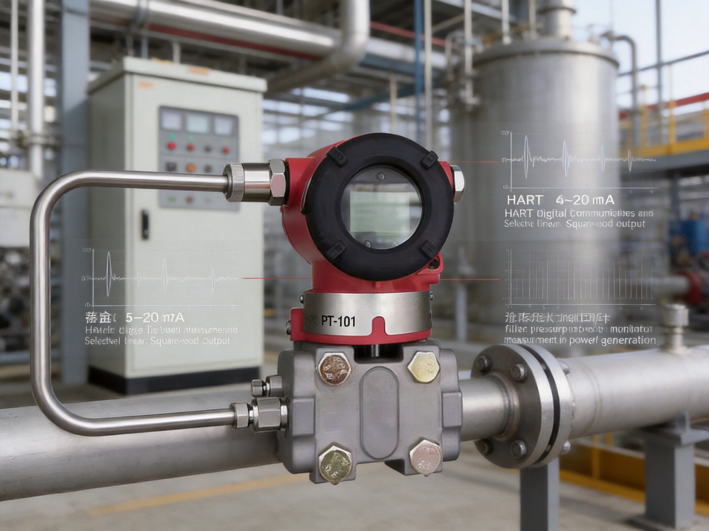
Material selection is one of the most important factors in differential pressure transmitter service. The wetted parts may be exposed to corrosive chemicals, high chloride concentrations, process condensate, hydrocarbons, steam, oxygen, pulp, wastewater, or other aggressive substances. The XG3051DP therefore provides several diaphragm and fill-fluid combinations.
The standard measuring capsule is stainless steel 316L, and the standard diaphragm material is 316L stainless steel. 316L provides useful corrosion resistance for many general industrial applications and is widely accepted in process instrumentation. For stronger chemical service, Hastelloy C, gold-plated 316L, FEP-coated 316L, or tantalum diaphragm options are available according to the model selection structure.
Hastelloy C may be selected when the process contains aggressive acids, alkaline substances, or other media that may attack 316L. Gold-plated diaphragms can be considered for applications in which hydrogen permeation or specialized chemical compatibility is a concern. FEP-coated diaphragms provide a protective fluoropolymer surface for selected corrosive services. Tantalum is available for particularly demanding chemical applications, subject to a detailed compatibility review.
Two principal fill-fluid options are identified: silicone oil and fluorinated oil. Fluorinated oil is suitable for selected applications that require a different fill-fluid chemistry, including certain oxygen-related or process compatibility requirements. The oil-free treatment option is intended for oxygen service and includes oil-free fill fluid, FKM seals, a pressure limitation below 6 MPa, and a temperature limitation below 60 degrees Celsius. Oxygen service must always be specified and prepared under controlled procedures because contamination can create serious safety risks.
The wetted seal material may be selected as NBR, FKM, or PTFE. NBR is suitable for many general-purpose applications. FKM offers improved resistance to a range of oils, fuels, and elevated temperatures. PTFE is selected when chemical resistance is a priority. Seal selection should be based on process composition, temperature, pressure, permeation behavior, and the requirements of the entire process connection assembly.
Food and pharmaceutical applications may require hygienic diaphragm structures or special process connections. The supplied specification notes that customized hygienic diaphragm structures can be provided. Such applications should be reviewed with the manufacturer before ordering so that surface finish, cleanability, sealing, dead-leg control, and applicable hygienic standards can be addressed.
The transmitter is specified for an ambient temperature range of -40 to 85 degrees Celsius. Versions equipped with an LCD and fluororubber O-ring have a narrower stated ambient range of -20 to 65 degrees Celsius, while versions with a display have specified storage and transport limits that differ from the standard version. These distinctions should be considered when the transmitter is installed outdoors, in cold regions, near furnaces, or in areas exposed to direct solar heating.
The rated working pressure is available in 16 MPa, 25 MPa, and 40 MPa versions. Certain low-range selections also include special rated working pressure options. The static pressure limit extends from 3.5 kPa absolute pressure up to the rated pressure, and the proof pressure can reach 1.5 times the rated pressure when applied to both sides simultaneously, as specified. The unidirectional overload limit is up to the rated pressure.
Pressure ratings should never be interpreted as permission to exceed the limits of the selected diaphragm, process flange, seals, impulse piping, valves, or connected equipment. The complete measurement assembly must be rated for the maximum operating, startup, shutdown, and upset conditions. Thermal expansion, water hammer, pump pulsation, blocked impulse lines, and accidental valve operation should be assessed during engineering review.
The IP67 housing protection class helps protect the transmitter against dust ingress and temporary immersion under defined test conditions. This makes the enclosure suitable for many outdoor and industrial environments when cable glands, covers, conduit entries, and installation orientation are correctly handled. IP protection is not a substitute for proper sealing or for a suitable hazardous-area installation method.
The XG3051DP uses a two-wire DC24V system. The electrical connection may be made through an M20 × 1.5 cable gland or through the housing option selected in the ordering code. The terminal block accepts conductors from 0.5 to 2.5 square millimeters. Wiring should be performed by qualified personnel in accordance with the site’s electrical standards and the transmitter’s hazardous-area requirements where applicable.
The operating power supply range is generally 12 to 42 VDC, with a higher minimum requirement of 15 VDC for versions with a backlit LCD. The power-supply voltage and loop resistance must satisfy the relationship specified for the instrument. In practical terms, the supply must provide enough voltage for the transmitter, the wiring resistance, safety barriers if used, signal isolators, and any other loop devices.
HART communication requires a compatible load, normally between 250 and 600 ohms. If the loop resistance is too low, digital communication may be unreliable. If it is too high, the transmitter may not receive sufficient operating voltage. A loop calculation should therefore be completed before installation, especially where long cables, intrinsic-safety barriers, or multiple series devices are involved.
The signal lines should be routed away from high-voltage power cables, variable-frequency drives, heavy motors, and other strong electromagnetic interference sources. Shielded instrumentation cable may be appropriate depending on the plant standard. Shielding and grounding should be implemented consistently to avoid ground loops. In explosion-proof installations, the housing must be reliably grounded and the specified cable entries must be used.
The transmitter provides selectable alarm behavior. The low-alarm current is 3.7 mA, the high-alarm current is 21 mA, and the no-alarm mode holds the valid current immediately before a fault. The default setting is high alarm. The selected fault mode should be coordinated with the control-system philosophy so that operators can distinguish a process condition from an instrument or wiring fault.
The process connection flange has NPT 1/4 and M10 internal threads on the two end faces. The product family provides several connection arrangements, including a standard connection without a bleed valve, versions with a bleed valve on the rear end face, upper-side or lower-side bleed-valve arrangements, and a vertical mounting flange with a bleed valve.
Bleed-valve position should be selected according to the process medium and the intended installation orientation. Liquid-service impulse lines may require arrangements that allow gas to be vented from high points. Gas-service lines may require liquid condensate to be removed from low points. For steam service, condensate pots and balanced impulse lines may be required to protect the transmitter and stabilize the measurement.
Optional process accessories include a stainless-steel oval flange with a 1/2-inch NPT internal thread, an M20 × 1.5 external-thread stainless-steel tee connector, and an M20 × 1.5 external-thread welding connector. These accessories can simplify connection to existing impulse piping or support different installation practices within a plant.
Mounting brackets are available in flat and bent configurations, manufactured from coated carbon steel or stainless steel. A bracket can help prevent process piping from carrying the weight or mechanical stress of the transmitter. It also makes the instrument easier to orient for display access, cable entry, and maintenance.
Changes in mounting position parallel to the diaphragm are specified to cause no zero drift. A position change greater than 90 degrees relative to the diaphragm surface may create a zero offset of less than 0.4 kPa, which can be corrected through zero adjustment. The mounting arrangement should therefore be finalized before calibration, and the instrument should be rechecked after installation if its orientation changes.
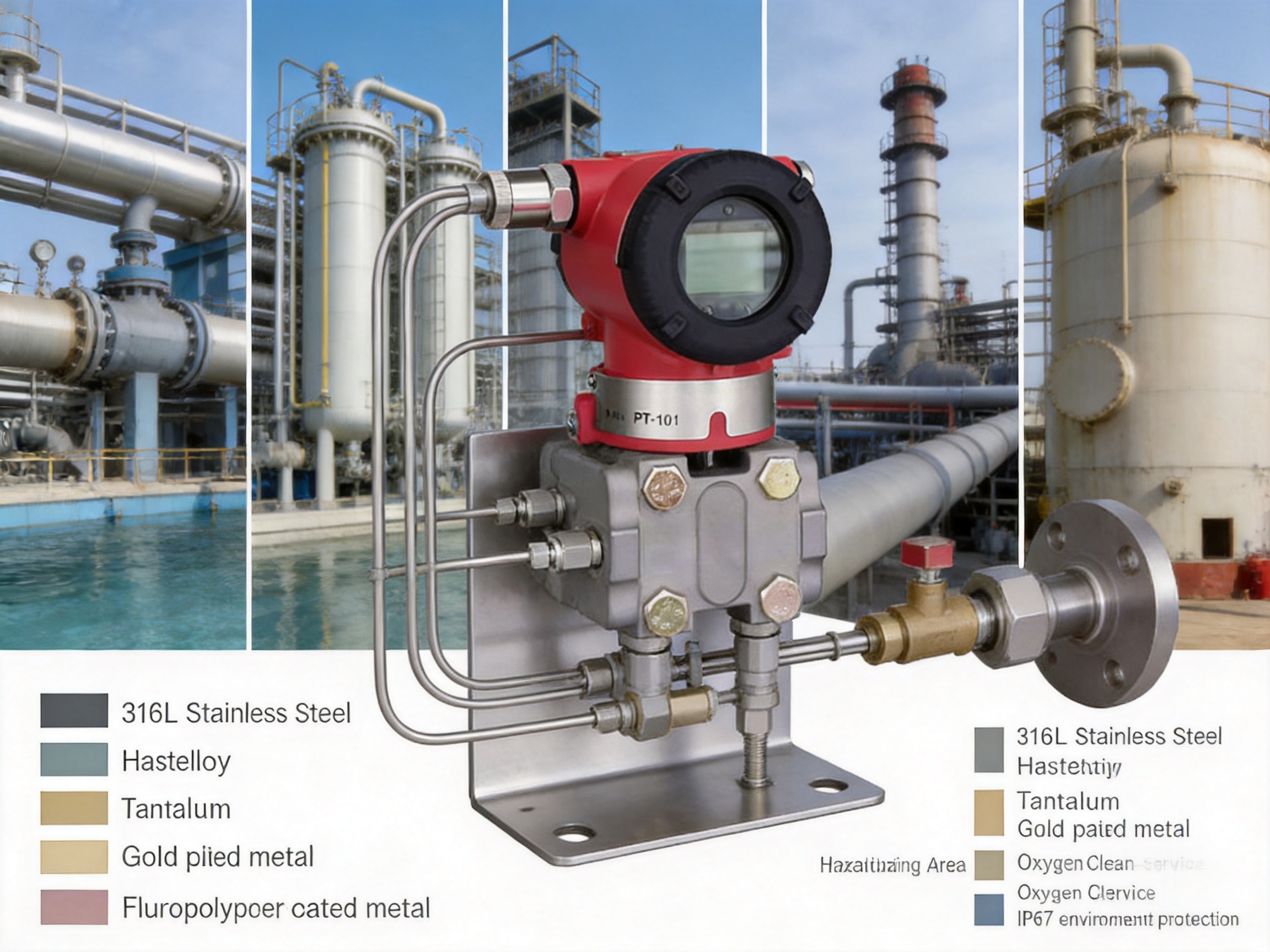
Petrochemical plants use differential pressure transmitters to monitor reactor level, tank level, pipeline flow, filter loading, and pressure loss across process equipment. The XG3051DP can be configured with corrosion-resistant diaphragms, suitable seal materials, and explosion-proof treatment for demanding areas. Its HART capability supports commissioning and maintenance in large plants where instrument access may be restricted.
In chemical service, the selected materials must match the actual medium rather than relying only on a general industry label. Concentration, temperature, chloride level, water content, pressure, and contamination can all affect corrosion behavior. The availability of Hastelloy C, tantalum, gold-plated, and coated diaphragm choices provides more flexibility than a standard 316L-only transmitter.
Power plants use differential pressure measurement for steam and water flow, boiler and turbine systems, furnace negative pressure, container level, and filter monitoring. High static pressure capability is important in many power applications because the differential measurement may be relatively small while the line pressure is high. Correct impulse-line design, isolation valves, condensate management, and overpressure protection are essential.
For boiler draft or furnace negative pressure, a low-range span code may be appropriate. For steam and water flow, a higher range may be selected depending on the primary flow element and design pressure. The transmitter’s adjustable damping can help reduce the effect of pulsation or short-term process fluctuations while retaining a usable control response.
Water and wastewater facilities use differential pressure measurement for tank level, pipeline flow, filter pressure loss, membrane systems, and purification processes. These installations often involve moisture, outdoor exposure, suspended solids, biological matter, and corrosive cleaning chemicals. The IP67 housing, configurable seal materials, and optional corrosion-resistant diaphragm choices are useful for these conditions.
Filter differential pressure measurement is a particularly common application. As a filter becomes blocked, the pressure difference between its inlet and outlet increases. The transmitter can send a 4–20 mA signal to a control system, activate an alarm, or initiate a maintenance procedure. If the process pressure and medium permit, the installation can be designed with isolation and bypass arrangements so that the transmitter can be serviced without shutting down the entire system.
Metallurgical processes often combine high temperature, dust, corrosive gases, slurry, and pressure fluctuation. Differential pressure measurements may be used for process pipelines, fluid pressure difference, vessel level, and gas or liquid flow. The transmitter should generally be connected through suitable impulse piping, cooling arrangements, separators, or remote process components when the process temperature or solids content exceeds the direct connection capability.
Where the process includes aggressive chemicals or high chloride concentrations, the selection of diaphragm and seal materials becomes especially important. A detailed material review before ordering can help reduce premature corrosion and measurement drift.
Pulp and paper plants use differential pressure transmitters for pulp level, filter pressure difference, and process flow. Pulp can be abrasive, fibrous, or chemically active, and process cleanliness may change rapidly. Proper connection design is needed to reduce plugging and ensure that the pressure signal represents the actual process condition. The transmitter’s adjustable range and damping functions can support stable measurement when the process has intermittent flow or pulsation.
The performance of an industrial transmitter depends not only on its design but also on how consistently it is manufactured, assembled, calibrated, and inspected. Xinguo Group Co., Ltd. operates as a group with businesses covering instrumentation, alloys, cables, precious metals, and instrument manufacturing. This structure provides access to materials knowledge and production capabilities that are directly relevant to industrial measurement products.
The company was founded in 1997 and is based in Tianchang City, Anhui Province, China. Its facilities cover more than 150 mu of land, with a construction area of approximately 60,000 square meters and a workforce of nearly 300 employees. More than 50 personnel are identified as professional technicians, senior technical experts, senior engineers, engineers, and assistant engineers.
The group’s manufacturing advantages include advanced equipment, modern production techniques, product development capability, and inspection procedures applied throughout the manufacturing process. For a pressure transmitter, this type of controlled approach is important because sensor assembly, diaphragm integrity, fill-fluid handling, electronic calibration, housing sealing, and final performance testing all influence field reliability.
Material control is another important strength. The company’s related alloy and precious-metal operations support its ability to work with industrial metals used in sensor components, thermocouples, protective materials, and specialized instrumentation. Although each transmitter configuration still requires appropriate incoming inspection and traceability, in-house materials expertise can improve the engineering response to demanding applications.
Xinguo Group has obtained ISO9001 Quality Management System, ISO14001 Environmental Management System, and GB/T28001 Occupational Health and Safety Management System certifications, according to the supplied company information. These systems indicate a structured approach to quality management, environmental responsibility, and occupational safety. The company also states that its products are designed to comply with IEC international standards as well as relevant national and industrial specifications.
The manufacturing process should be understood as a sequence of controlled activities rather than a single assembly operation. It begins with specification review and material selection. Components are then processed or procured according to defined requirements. The sensing capsule, diaphragms, seals, process flange, electronics, and housing are assembled. Electrical connections and sealing surfaces are checked, and the completed transmitter is calibrated against reference equipment.
Final testing may include output verification, range adjustment, zero stability, pressure testing, insulation or electrical checks, communication verification, enclosure inspection, and visual examination. Product options such as HART, LCD, explosion-proof treatment, square-root output, special diaphragms, and oil-free preparation require additional configuration checks. Consistent documentation is essential so that the delivered instrument matches the customer’s order code and application requirements.
This manufacturing and quality approach gives the XG3051DP an advantage over low-cost generic transmitters that may offer limited configuration, inconsistent material selection, or inadequate documentation. It also supports more effective technical communication with international customers who need a complete solution rather than a basic electronic pressure sensor.
The model code allows the purchaser to define the major characteristics of the transmitter. Accuracy options include basic errors of ±0.05 percent, ±0.075 percent, and ±0.1 percent. Output options include 4–20 mA with HART communication or 4–20 mA analog output. Range codes cover the pressure spans described earlier.
Diaphragm and fill-fluid selections include 316L with silicone oil, 316L with fluorinated oil, Hastelloy C with silicone or fluorinated oil, gold-plated 316L, FEP-coated 316L, and tantalum with silicone oil. Rated working pressure selections include 16 MPa, 25 MPa, and 40 MPa, with additional low-range options identified for particular span codes.
Process connection choices cover standard NPT and M10 threaded holes, several bleed-valve positions, and a vertical mounting arrangement. Wetted seal options include NBR, FKM, and PTFE. Housing choices include aluminum with protective coating or stainless steel, with either 1/2-inch NPT or M20 × 1.5 cable entry depending on the selected version.
Special functions include no special function, square-root output, lightning protection, and oil-free treatment. Mounting brackets, process connection accessories, LCD or OLED displays, intrinsically safe treatment, flameproof treatment, cable entry devices, low-voltage versions, lightning protection modules, oil-free degreasing, and factory test reports can also be specified.
| Selection Area | Available Examples | Selection Consideration |
|---|---|---|
| Output | 4–20 mA; 4–20 mA with HART | Match the DCS, PLC, or maintenance communicator |
| Diaphragm | 316L, Hastelloy C, gold-plated 316L, FEP-coated 316L, tantalum | Review corrosion, permeation, temperature, and cleaning conditions |
| Fill fluid | Silicone oil, fluorinated oil | Confirm process compatibility and special service requirements |
| Seal | NBR, FKM, PTFE | Consider temperature, chemicals, and permeation |
| Housing | Coated aluminum or stainless steel | Match site environment and mechanical requirements |
| Special function | Square root, lightning protection, oil-free treatment | Choose according to process and safety requirements |
| Display | No display, backlit LCD, OLED | Consider local visibility and ambient temperature |
| Hazardous area | None, intrinsically safe, flameproof | Match the area classification and installation method |
Before commissioning, verify the nameplate data, range code, process connection, diaphragm material, seal material, output type, and hazardous-area marking. Confirm that the process pressure and temperature are within the ordered configuration. Check that the impulse lines are correctly connected to the high- and low-pressure sides and that isolation valves, equalizing valves, vents, and drains are arranged correctly.
For a new installation, flush or clean the impulse lines according to the process requirements. Remove air from liquid-service lines and remove liquid accumulation from gas-service lines where appropriate. For steam service, ensure that condensate levels are balanced and that the transmitter is protected from direct high-temperature steam. Do not expose the diaphragm to mechanical damage, uncontrolled pressure shock, or unsuitable cleaning tools.
Zero adjustment should be performed under the correct reference condition. If both sides of the transmitter are exposed to the same pressure and the process arrangement permits it, a zero check can be completed through the equalizing system. Calibration should use equipment with suitable accuracy and pressure capability. HART communication can be used to adjust zero, range, damping, alarm mode, and square-root settings.
When a signal is inaccurate or shows excessive zero drift, the first inspection should focus on the impulse piping. Leaks, blockages, fluid accumulation, incorrect valve positions, and unequal temperature conditions are common causes. Range migration errors, sudden environmental temperature changes, and overpressure impact can also affect the output. After the physical cause is corrected, recalibrate zero and range with an approved HART controller or calibration system.
Maintenance intervals should be determined by process severity, historical drift, regulatory requirements, and the importance of the measurement. Periodic checks may include visual inspection, housing and cable-entry inspection, zero verification, loop-current verification, process-connection inspection, and communication testing. In corrosive applications, inspect the diaphragm and wetted seals for signs of attack or deterioration.
The XG3051DP is positioned between basic analog pressure sensors and more expensive high-end imported smart transmitters. Compared with a simple analog sensor, it provides adjustable ranging, selectable output behavior, optional HART communication, alarm-current configuration, damping adjustment, multiple diaphragm materials, and broader process customization.
Compared with a fixed-range transmitter, the XG3051DP offers a broader engineering margin. Its range can be adjusted within the selected upper and lower limits, and the user can select from multiple span codes. This makes it more adaptable when the process design changes or when a plant standardizes several measurement points around one product family.
Compared with a transmitter that provides only stainless-steel wetted parts, the XG3051DP offers additional material options for corrosive or specialized service. Hastelloy C, tantalum, FEP-coated, and gold-plated diaphragms can address applications where standard 316L may be insufficient. The availability of fluorinated fill fluid, FKM, PTFE, and oil-free treatment further expands the application range.
Compared with an imported premium transmitter, the XG3051DP can offer a cost-effective alternative while retaining important industrial functions, including HART communication, intelligent configuration, high static-pressure capability, IP67 protection, multiple process connections, and hazardous-area options. The most appropriate comparison should consider the complete specification, documentation, calibration support, replacement availability, local technical service, and lifecycle cost rather than purchase price alone.
The XG3051DP is primarily a differential pressure transmitter. It measures pressure difference between its high- and low-pressure connections. Through suitable installation and configuration, it can also be used for pipeline flow, closed-vessel liquid level, filter pressure difference, furnace negative pressure, and other differential-pressure-based measurements.
No. The XG3051DP is designed for differential pressure measurement. Absolute pressure requires an instrument with an absolute-pressure sensing reference. A differential pressure transmitter can be used in a system where one side is connected to a reference pressure, but the resulting measurement must be engineered and interpreted correctly.
The square-root function is normally selected when differential pressure is being used to calculate flow through a suitable primary flow element. It should not be activated simply because the process contains a pressure difference. The primary device, piping arrangement, fluid behavior, and control-system requirements should be reviewed first.
Common causes include leaks, blockages, fluid accumulation, incorrect range-migration settings, sudden ambient-temperature changes, and diaphragm overpressure. Inspect the impulse lines, valves, seals, and process connections first. Once the physical problem has been corrected, check zero and range with a suitable calibrator or HART controller.
The standard two-wire transmitter is designed for a DC supply generally within 12 to 42 VDC. Versions with a backlit LCD require a higher minimum supply of 15 VDC. The actual supply must also account for loop resistance, cable length, safety barriers, signal isolators, and the requirements of HART communication.
The specified digital communication load range is 250 to 600 ohms. A 250-ohm resistor is commonly connected in series with the loop when required by the control-system design. The complete circuit should be calculated so that the transmitter receives sufficient operating voltage.
316L may be unsuitable for some highly corrosive media, particularly where strong acids, strong alkalis, or high chloride levels are present. Hastelloy C, tantalum, FEP-coated 316L, or other special materials may be considered. The correct choice depends on concentration, temperature, pressure, contaminants, and exposure time, so a compatibility review is recommended.
Yes, the transmitter has an IP67 housing protection class and an ambient temperature range extending from -40 to 85 degrees Celsius for the standard version. Cable entries, covers, grounding, drainage, and mounting orientation must still be handled correctly. Display-equipped versions may have different temperature limits.
A bleed valve can assist with venting trapped gas, draining accumulated liquid, or supporting commissioning and maintenance, depending on the process and mounting orientation. The valve position should be selected according to whether the process is liquid, gas, steam, or a mixed-phase service.
Hazardous-area options include intrinsically safe and flameproof treatment under the stated selection structure. The complete installation must comply with the applicable area classification, equipment certification, barrier requirements, cable-entry requirements, grounding rules, and site safety procedures. The transmitter must not be installed in a hazardous area using an unsuitable version or cable gland.
Determine the normal operating differential pressure, minimum and maximum expected values, static pressure, overpressure conditions, and required accuracy. Select the span code with the lowest practical turndown ratio while leaving sufficient margin for abnormal operating conditions. A span that is unnecessarily wide can reduce effective performance.
Mounting changes parallel to the diaphragm are specified to cause no zero drift. A change greater than 90 degrees relative to the diaphragm surface can produce a zero offset of less than 0.4 kPa. This offset can normally be corrected with zero adjustment, but the final orientation should be established before calibration.
Maintenance typically includes inspection of the housing, cable entries, process connections, impulse lines, isolation valves, and seals. Periodic zero checks, loop verification, HART communication checks, and calibration should be scheduled according to process severity and measurement criticality. Corrosive services require additional attention to diaphragm and seal condition.
The XG3051DP Differential Pressure Transmitter is a versatile instrument for industrial measurement systems that require reliable differential pressure, flow, or level information. Its capacitive sensing principle, 4–20 mA output, optional HART communication, configurable linear or square-root output, broad range structure, and adjustable damping make it suitable for integration into modern and established control systems.
Its material flexibility is a significant advantage. Users can select 316L, Hastelloy C, gold-plated 316L, FEP-coated 316L, or tantalum diaphragms, together with silicone or fluorinated fill fluid and NBR, FKM, or PTFE seals. These choices enable more appropriate adaptation to corrosive, high-pressure, oxygen-related, hygienic, and general industrial applications.
The instrument also provides practical mechanical and environmental features, including IP67 protection, multiple rated working pressures, optional display units, process connection accessories, mounting brackets, lightning protection, oil-free treatment, and hazardous-area versions. This level of configuration allows the transmitter to be engineered for the actual plant rather than selected only as a generic pressure device.
Behind the product is a manufacturing organization with experience in industrial instrumentation, alloys, cables, precious metals, and electrical accessories. Xinguo Group’s technical personnel, manufacturing facilities, quality systems, inspection procedures, and international-oriented product development support the consistent production of process instruments for global customers.
For plants seeking a cost-effective and adaptable alternative to conventional or higher-priced imported transmitters, the XG3051DP offers a balanced combination of measurement performance, application flexibility, material options, intelligent communication, and manufacturing capability. Correct selection, installation, calibration, and maintenance remain essential, but when these engineering practices are followed, the transmitter can provide dependable service across a wide range of industrial processes.
1. XG3051DP Differential Pressure Transmitter Product Specification and Model Selection Information.
2. Industrial Process Measurement Principles: Differential Pressure, Flow, and Level Applications.
3. General Requirements for Two-Wire 4–20 mA Industrial Instrument Loops.
4. HART Communication and Smart Transmitter Commissioning Practices.
5. Industrial Pressure Instrument Materials and Corrosion-Resistance Selection Guidelines.
6. Electromagnetic Compatibility Test Information for Industrial Measurement Equipment.
7. Quality Management, Environmental Management, and Occupational Health and Safety System Information supplied by the manufacturer.



 INQUIRY
 English
 عربى
 русский
 中文简体