Accurate flow measurement is essential for modern industrial production. Steam distribution, compressed-air management, process-gas monitoring, water control, energy settlement, and chemical production all depend on dependable measurement instruments. A flowmeter must do more than display an instantaneous value. It must remain stable under changing operating conditions, provide useful communication signals, minimize pressure loss, support convenient installation, and continue operating with limited maintenance.
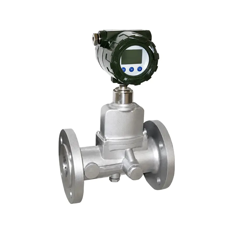
The XG-LUGB series intelligent vortex flowmeter is designed to meet these requirements through the Karman vortex measurement principle, integrated digital processing, multiple output options, and a range of installation structures. It is suitable for measuring the volume flow rate and, when appropriate compensation parameters are available, the mass flow rate of liquids, gases, saturated steam, and superheated steam.
The instrument is available in flanged wafer configurations for nominal diameters from DN25 to DN300 and insertion configurations for nominal diameters from DN300 to DN2000. Its measurement capabilities, intelligent electronics, flexible compensation functions, and industrial construction make it suitable for thermal energy management, petrochemical processing, food and pharmaceutical production, municipal utilities, and general process automation.
This article explains the operating principle, product advantages, configuration options, installation requirements, manufacturing strengths, application value, and selection considerations associated with the XG-LUGB series.
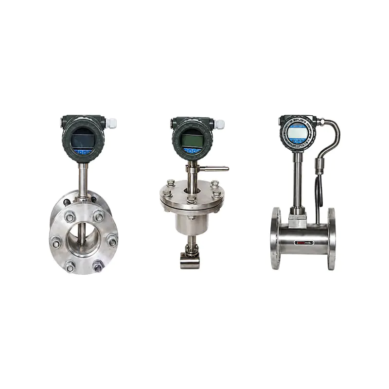
XG-LUGB series intelligent vortex flowmeter
Industrial flow measurement is often performed in environments where the medium may be hot, pressurized, corrosive, compressible, or subject to variable operating conditions. Steam pipelines may experience changing temperature and pressure. Compressed-air systems may have pulsation and demand fluctuations. Process-gas lines may operate across a broad flow range. Water and low-corrosive liquids may require continuous monitoring for production control or energy accounting.
Different flowmeter technologies are suited to different media. Electromagnetic flowmeters are highly effective for conductive liquids, but they are not suitable for gases or steam. Mechanical meters may contain moving parts that wear over time. Thermal flowmeters can be useful for gases but may require careful consideration of gas composition and heat-transfer conditions. Differential-pressure meters can be widely applied, but their permanent pressure loss and associated energy consumption may be significant.
Vortex flowmeters occupy an important position because they can measure liquids, gases, and steam with one basic measurement technology. They do not require internal moving mechanical parts, and their operating principle is compatible with many general-purpose industrial pipelines. When combined with temperature and pressure compensation, a vortex meter can provide more meaningful process information for compressible media and steam applications.
The XG-LUGB series extends this basic principle with an intelligent electronics platform. The local LCD can display several process parameters, while outputs such as 4–20 mA, pulse, HART, and RS485 communication support connection to PLC, DCS, SCADA, energy-management, and plant-monitoring systems.
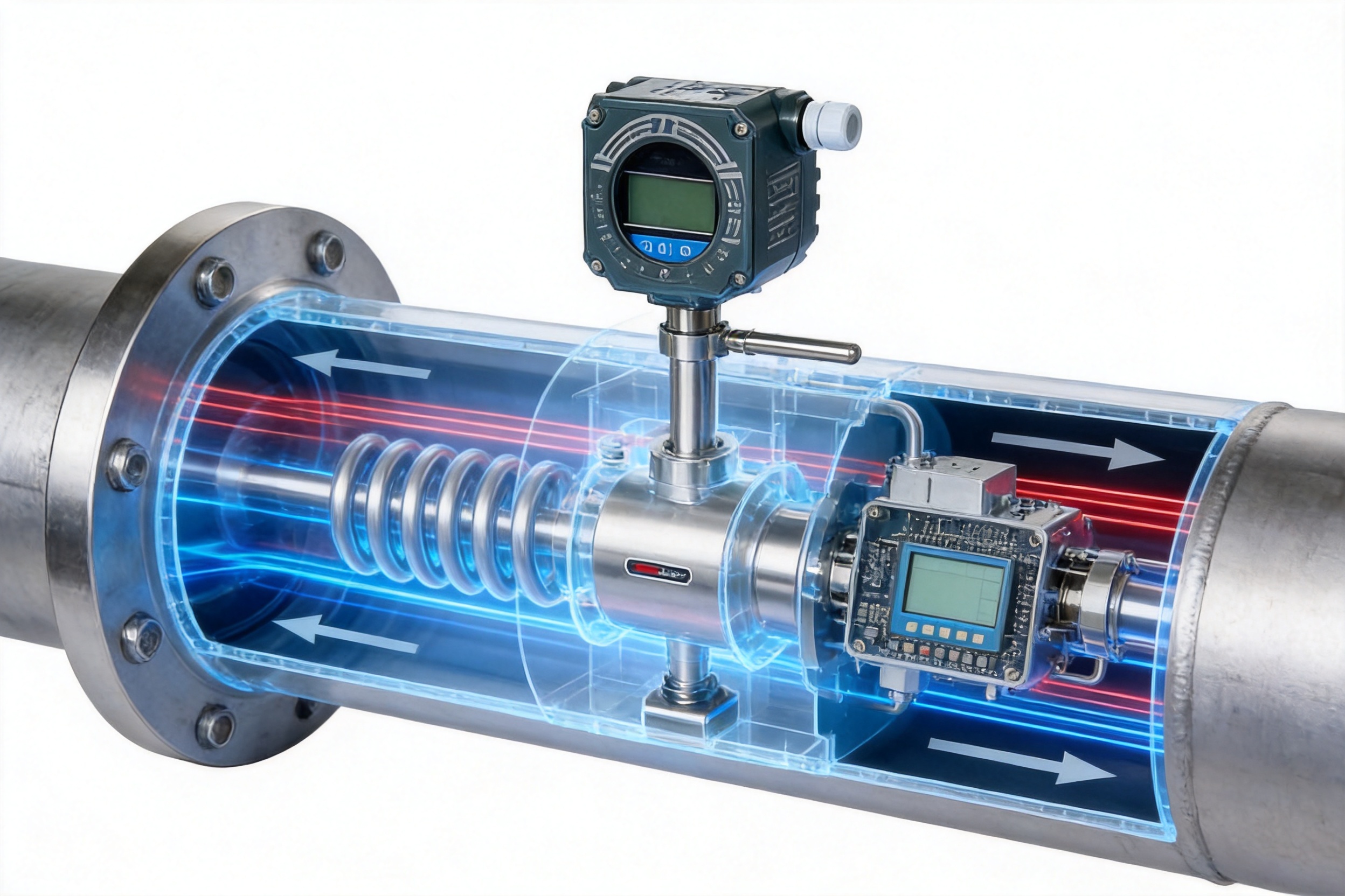
When a fluid flows around a bluff body placed in a pipeline, alternating vortices are created downstream. This repeating pattern is known as a Karman vortex street. Within the appropriate operating range, the vortex frequency is related to the velocity of the medium passing through the pipe.
The sensor inside a vortex flowmeter detects the pressure or force fluctuation produced by the vortices. The electronic unit then converts the detected frequency into a flow signal. After the internal parameters are set for pipe size, medium type, density, temperature, pressure, and calibration conditions, the instrument calculates and displays the required flow information.
For a simplified description, the vortex frequency is proportional to the average flow velocity:
f = St × V / d
In this relationship, f represents vortex frequency, St represents the Strouhal number, V represents flow velocity, and d represents the characteristic width of the vortex-generating body. The electronic system uses this relationship together with calibration data and configuration parameters to calculate flow.
The vortex frequency is fundamentally related to volumetric flow. For gases and steam, mass flow or standardized volume flow may require additional information because density changes with pressure and temperature. The XG-LUGB series can support temperature and pressure compensation configurations, allowing the instrument to calculate compensated values when the application and selected configuration require them.
The use of piezoelectric crystal detection components provides a compact and reliable way to detect vortex signals. The stated operating temperature range for the detection assembly is approximately -20 to 280 degrees Celsius, subject to the specific product configuration and installation conditions.
A major advantage of a vortex flowmeter is the absence of traditional internal moving parts such as impellers, gears, or rotating shafts. The XG-LUGB series uses a fixed vortex-generating structure and an electronic detection system. This reduces mechanical wear and helps lower the maintenance workload during long-term operation.
A simpler internal structure can also reduce the number of components that may require periodic replacement. In applications where the measured medium is clean and the instrument is correctly installed, the flowmeter can provide stable service without the mechanical maintenance associated with rotating meters.
The housing can be supplied in stainless steel or carbon steel. Stainless steel is appropriate where improved corrosion resistance or a more durable external structure is desired. Carbon steel can be considered for general industrial environments where the process and surrounding conditions are compatible with that material.
The XG-LUGB series is designed for liquids, gases, saturated steam, and superheated steam. This gives the product a broad application range compared with technologies limited to a particular physical property of the medium.
Typical liquid applications include water and low-corrosive process liquids. Gas applications include compressed air and general industrial gases. Steam applications include boiler steam, process steam, saturated steam, and superheated steam. Before selection, the user should confirm the medium composition, viscosity, temperature, pressure, cleanliness, and tendency to form deposits.
The instrument is not intended for media containing large amounts of solid particles or for highly viscous media that are prone to scaling. Solids, deposits, and heavy contamination can interfere with vortex formation and sensor operation. They may also damage or obstruct the probe. In such applications, filtration, upstream process improvement, special construction, or an alternative flowmeter technology may be necessary.
The stated measurement range ratio can reach approximately 10:1 in standard applications and may be extended in special cases after engineering evaluation. A wide range is valuable when a pipeline experiences changing production loads, seasonal demand, variable steam consumption, or intermittent equipment operation.
For example, a thermal distribution system may operate at a high flow rate during peak production and at a much lower flow rate during standby operation. A flowmeter with a narrow usable range may lose accuracy or become unstable during low-demand periods. A correctly selected vortex meter can cover a broader portion of the operating profile.
Rangeability should not be considered in isolation. The actual usable range depends on medium density, viscosity, pressure, temperature, pipe diameter, minimum Reynolds number, vibration, installation conditions, and the required accuracy. The final selection should be based on the lowest and highest expected operating flow rates rather than only the nominal pipe size.
The XG-LUGB series is designed to produce relatively low pressure loss compared with flow technologies that use substantial permanent throttling elements. Lower pressure loss can reduce the energy required to move a medium through a process line.
This characteristic is especially relevant in compressed-air systems, gas distribution, circulating-water systems, and steam networks. Even a small pressure loss repeated across many measurement points can contribute to operating costs. A flowmeter that provides the required signal while minimizing unnecessary resistance can support more efficient system design.
Lower pressure loss also helps preserve the available pressure margin in a process. However, the actual pressure loss depends on the meter size, flow velocity, density, pipe geometry, and process conditions. Users should evaluate the complete operating point during technical selection.
The instrument uses a low-power CPU and LCD display. Depending on the configuration, the local display can show temperature, pressure, instantaneous flow rate, cumulative flow, density, and frequency. This gives operators access to useful process information at the installation point without requiring an external control system.
Local indication is particularly valuable during commissioning, routine inspections, equipment troubleshooting, and energy audits. Operators can compare the displayed value with control-room data and investigate wiring, communication, or configuration issues more efficiently.
The intelligent electronics also support parameter setting through a password-protected menu. A hidden-button design helps reduce accidental operation and discourages unauthorized modification of key parameters. This is useful in plants where instrument settings need to be controlled as part of quality, safety, or process-management procedures.
The XG-LUGB series can be supplied as a battery-powered local display type, a battery-powered remote-transmission type, or an externally powered remote-transmission type. The battery-powered local version is designed for low energy consumption, with a stated battery life of up to two years under suitable operating conditions.
Battery operation can simplify installation in locations where external power is difficult to provide. It may be useful for utility pipelines, remote sections of a plant, temporary monitoring points, or retrofit projects where new cable installation would be expensive.
For process-control applications requiring continuous analog output or digital communication, an externally powered configuration can be selected. A dual-supply option combining an internal battery and external 24 V supply is also included in the selection system. The actual available functions depend on the selected output and power-supply combination.
The product supports digital pulse output and two-wire 4–20 mA current output. HART communication is available, and an RS485 communication interface supports digital data transmission, including Modbus-based integration where configured.
The 4–20 mA output is widely used in industrial control systems because it is robust over long cable distances and easy to integrate with PLC and DCS analog input modules. Pulse output can be used for cumulative flow counting, totalizer systems, or external flow-processing equipment. HART communication can provide access to additional parameters and diagnostic information through compatible host systems.
RS485 communication is useful where multiple instruments need to communicate over a digital network. It can reduce the amount of point-to-point wiring and facilitate centralized data collection. Before installation, the user should confirm communication protocol settings, address assignment, cable specifications, grounding, termination, and compatibility with the supervisory system.
The product includes a real-time data storage function intended to prevent internal data from being lost under normal abnormal-power or operating situations. This feature is important for cumulative flow records and stored configuration information.
Data retention is valuable in energy-management applications, particularly where steam, compressed air, gas, or circulating water consumption must be reviewed over time. It can also assist maintenance personnel in checking whether a change in process operation corresponds to a change in measured flow.
The data-storage function should be understood as part of the instrument’s internal operating design. Users should still establish an appropriate plant-level data backup and reporting system for critical measurement records.
The XG-LUGB selection system allows users to specify the nominal diameter, measured medium, structure type, signal output, compensation mode, temperature class, pressure class, operating environment, power supply, and flow range.
| Configuration Item | Available Options | Selection Consideration |
|---|---|---|
| Measured medium | Liquid, gas, steam | Choose according to the physical state and operating conditions of the process medium. |
| Structure type | Wafer flanged, simple insertion, ball-valve insertion, high-pressure, submersible, corrosion-proof | Choose according to pipe size, maintenance needs, pressure, environment, and installation method. |
| Signal output | Default output, 4–20 mA, pulse, HART, RS485 | Match the interface to the PLC, DCS, SCADA, energy-management, or metering system. |
| Compensation mode | None, temperature, pressure, temperature and pressure | Use compensation when accurate density correction is required for gases or steam. |
| Temperature class | Low temperature, high temperature | Low-temperature applications are generally specified at or below 80 degrees Celsius; high-temperature applications are generally specified at or above 80 degrees Celsius. |
| Pressure class | Normal pressure, high pressure | Verify operating and design pressure before selecting the sensor construction. |
| Operating environment | Normal environment, explosion-proof environment | Choose the suitable protection configuration for the hazardous-area classification. |
| Power supply | Internal battery, battery plus external 24 V, 24 VDC only | Consider output requirements, wiring availability, and operating location. |
The wafer flanged type is available for nominal diameters from DN25 to DN300. Its compact construction can be suitable for installations where space is limited or where the meter is installed between existing flanges.
Proper flange alignment is important. The internal bore must be centered with the pipeline, and gaskets should not project into the flow path. Incorrect alignment may disturb the velocity profile and create measurement error. The pipeline should also be adequately supported so that mechanical loads are not transferred to the meter body.
The insertion type is designed for larger pipelines from approximately DN300 to DN2000. Instead of occupying the full pipe cross-section, the sensor is inserted into the pipeline. This can reduce equipment cost and installation complexity for large-diameter lines.
Insertion meters require careful attention to insertion depth, sensor orientation, pipe internal diameter, flow profile, and installation location. The stated flow ranges for insertion models are based on flow velocity at the insertion center point and should not be interpreted in exactly the same way as full-bore meter ranges.
Simple insertion and ball-valve insertion structures are included in the selection system. A ball-valve design may offer additional convenience for installation or maintenance in suitable pressurized pipeline applications, but the pressure rating, isolation procedure, and safety requirements must be verified before work begins.
The selection table includes high-pressure, submersible, and corrosion-proof structure types. These options allow the product family to address a broader set of field conditions than a single standard housing could support.
Standard sensor nominal pressure is listed from 1.0 MPa to 4.0 MPa, while high-pressure sensor versions are listed from 6.3 MPa to 42 MPa as special-order configurations. The selected pressure rating must be higher than the maximum operating pressure and compatible with temperature, pressure surges, flange standards, and applicable safety regulations.
Submersible or specially protected configurations may be considered for outdoor, damp, or flood-prone locations. The corrosion-proof option may be considered when the surrounding environment or process material requires improved resistance. The exact wetted materials, sealing materials, and compatibility should be confirmed with the technical specification for the intended medium.
The following values summarize the supplied flow-range information. Exact performance depends on the medium, density, temperature, pressure, installation conditions, and final calibration. The table should be used for preliminary selection, followed by technical confirmation.
| Model | Nominal Diameter | Liquid Range, cubic meters per hour | Gas Range, cubic meters per hour | Steam Range, cubic meters per hour |
|---|---|---|---|---|
| XG-LUGB-25 | DN25 | 1.0–12 | 8.8–124 | 7–124 |
| XG-LUGB-32 | DN32 | 1.5–20 | 15–200 | 12–200 |
| XG-LUGB-40 | DN40 | 2.0–26 | 23–300 | 18–300 |
| XG-LUGB-50 | DN50 | 3–56 | 35–450 | 28–450 |
| XG-LUGB-65 | DN65 | 4.8–96 | 63–820 | 50–820 |
| XG-LUGB-80 | DN80 | 7.2–145 | 90–1200 | 75–1200 |
| XG-LUGB-100 | DN100 | 11–224 | 142–1950 | 120–1950 |
| XG-LUGB-125 | DN125 | 18–352 | 220–3000 | 175–3000 |
| XG-LUGB-150 | DN150 | 26–512 | 320–4400 | 260–4400 |
| XG-LUGB-200 | DN200 | 45–920 | 565–7800 | 440–7800 |
| XG-LUGB-250 | DN250 | 70.4–1200 | 850–12400 | 720–12400 |
| XG-LUGB-300 | DN300 | 100–2020 | 1250–17500 | 1020–17500 |
For insertion-type models, the supplied data extends from DN300 to DN2000. The listed liquid ranges include approximately 127–1650 cubic meters per hour for DN300, 226–2950 for DN400, 353–4600 for DN500, 510–6620 for DN600, 910–11800 for DN800, 1450–18500 for DN1000, 2050–26650 for DN1200, 3200–40300 for DN1500, and 5600–71400 for DN2000. Gas and steam ranges increase correspondingly with pipeline size and operating conditions.
Vortex flowmeters require a reasonably developed and stable velocity profile. Bends, valves, pumps, reducers, expanders, strainers, and other disturbances can create swirl or uneven velocity distribution. If the meter is installed too close to these components, the detected vortex signal may become unstable or biased.
As a general guideline, the upstream straight-pipe length should be approximately 15 to 20 pipe diameters, while the downstream straight-pipe length should be approximately 5 to 10 pipe diameters. The exact requirement depends on the disturbance type, meter design, pipe arrangement, and applicable installation standard.
Where space is limited, the user should consult the installation drawing and technical team rather than simply reducing the straight length. A poor installation can create reading fluctuation even when the meter itself is functioning correctly.
Vibration is one of the common causes of unstable vortex flow readings. Pumps, compressors, reciprocating equipment, control valves, unsupported pipe sections, and nearby rotating machinery can transmit vibration to the meter.
The pipeline should be properly supported on both sides of the instrument. The meter should not be used as a structural support. Where necessary, vibration sources should be isolated or flexible connections should be evaluated. However, flexible connections must not create excessive movement or misalignment at the meter.
The pipeline should be full during measurement. Liquid applications should be arranged to prevent partial filling, excessive aeration, or the accumulation of gas pockets near the sensor. Gas and steam systems should be designed to avoid liquid carryover, condensation accumulation, and two-phase flow unless the instrument has been specifically engineered for those conditions.
Large quantities of bubbles in a liquid can produce flow-reading fluctuation. In gas and steam lines, droplets or slugs may similarly disturb measurement. Separators, drainage points, condensate management, or changes in meter location may be required to improve process conditions.
The user must verify both normal and extreme temperature and pressure conditions. High-temperature steam service may require the high-temperature sensor configuration. Pressure should be compared with the standard or high-pressure sensor rating, including possible pressure surges.
For compressible media, temperature and pressure influence density. If the process requires mass flow or compensated volume flow, the instrument should be ordered with the appropriate compensation mode and external or integrated sensing arrangement. The selected pressure and temperature instruments must be correctly located and calibrated.
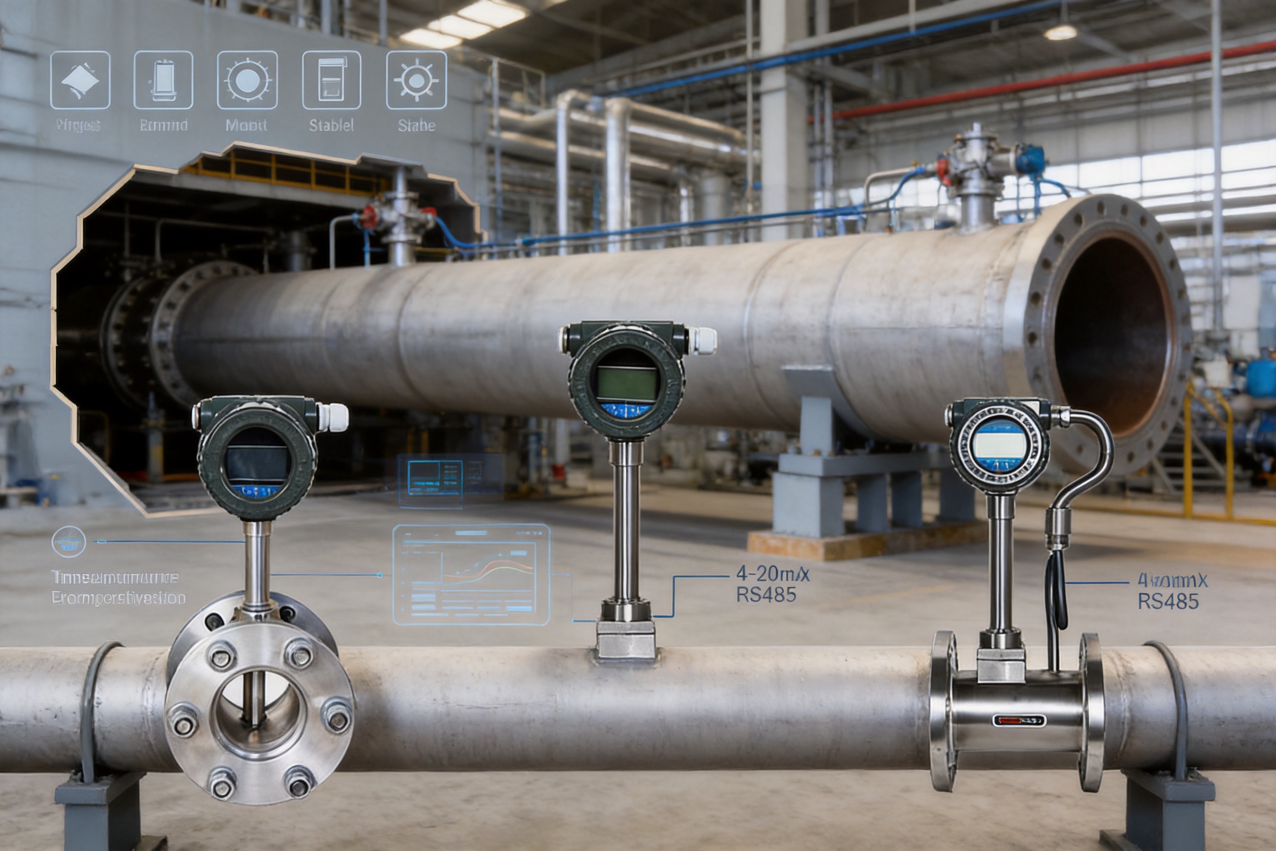
For liquids with relatively stable density, volumetric flow may be sufficient for process control. For gases and steam, however, density can change considerably with pressure and temperature. Reporting only actual volume flow may not provide an accurate basis for energy settlement, production accounting, or mass-balance calculations.
Temperature compensation corrects the flow calculation according to measured or configured temperature. Pressure compensation corrects the calculation according to measured or configured pressure. Combined temperature and pressure compensation can provide a more complete density correction for applications where both variables change significantly.
The selection system includes four compensation choices: no compensation, temperature compensation only, pressure compensation only, and temperature-and-pressure compensation. The correct choice depends on the medium and the required output value. Users should clearly define whether they need actual volume, standard volume, mass flow, or energy-related information before ordering.
In steam applications, the distinction between saturated and superheated steam is especially important. Steam tables or a suitable calculation model may be required to determine density and enthalpy. The flowmeter should be configured with parameters appropriate to the actual process state.
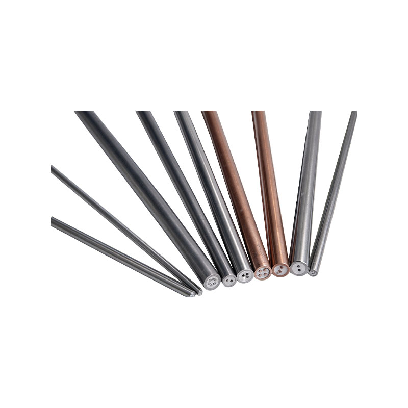
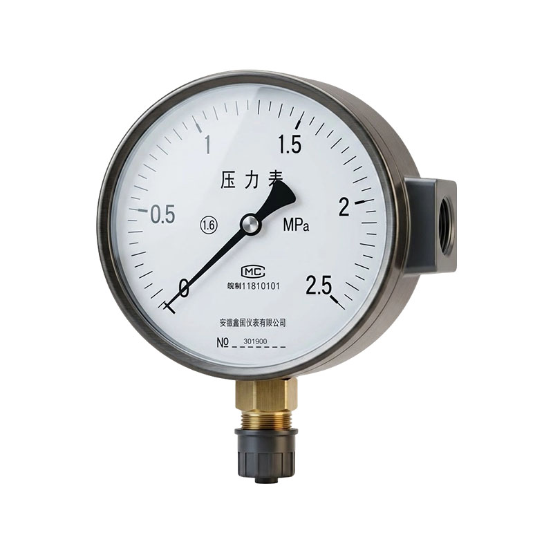
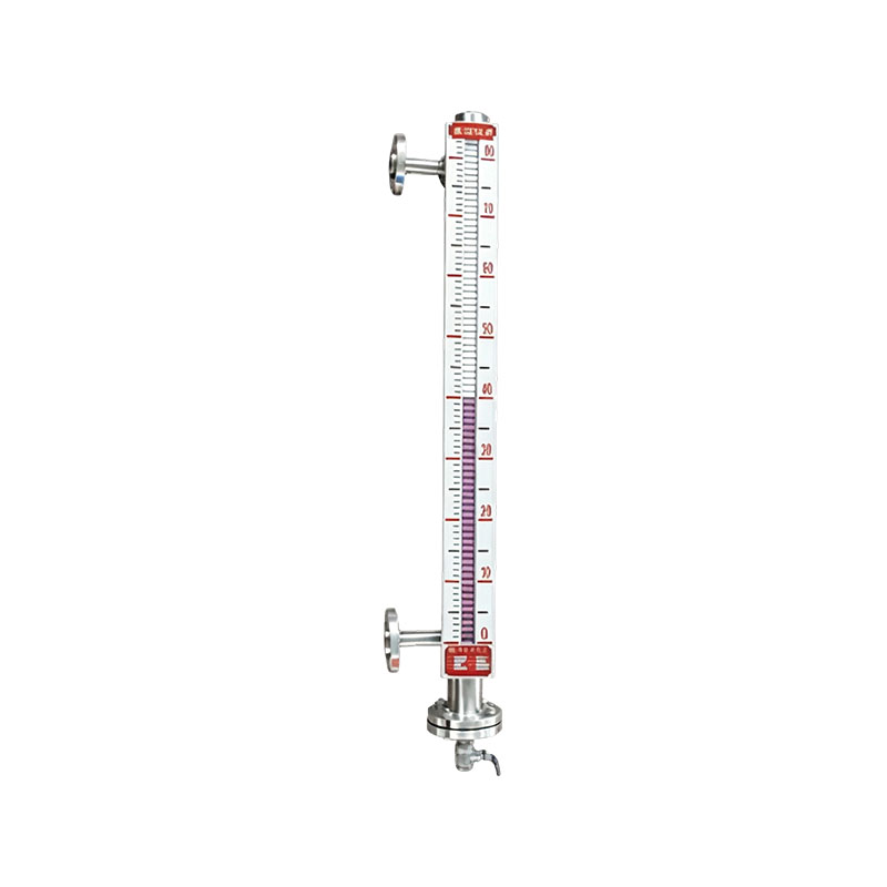
The manufacturer is a national high-technology enterprise with business activities covering temperature instruments, pressure instruments, flowmeters, level instruments, alloy materials, cables, and electrical accessories. This broad product structure is valuable because flow measurement systems often need to work together with temperature sensors, pressure transmitters, pressure gauges, thermocouples, signal cables, and control equipment.
An organization that develops both instruments and related materials can coordinate technical requirements across product categories. For example, a steam measurement system may require a vortex flowmeter, temperature measurement, pressure measurement, compensation, cable connection, and control-system integration. A broader manufacturing base can support more consistent project coordination than a single-product supplier.
The company was founded in 1997 and has developed a technical organization that includes professional technicians, senior technical experts, senior engineers, engineers, and assistant engineers. Its stated research and development capabilities support product design, process improvement, testing, and customized application work.
For an intelligent flowmeter, technical capability extends beyond mechanical fabrication. It includes sensor design, signal processing, digital compensation, low-power electronics, communication interfaces, display software, enclosure protection, calibration, and application engineering. These areas must operate together for the final instrument to deliver dependable field performance.
The manufacturer reports the use of advanced equipment, modern production techniques, and inspection procedures at every stage of manufacturing. This is important for flowmeters because performance depends on dimensional accuracy, sensor installation, electronic assembly, sealing, calibration, and final verification.
Manufacturing control may include incoming-material inspection, machining or forming control, sensor assembly, circuit-board inspection, enclosure and sealing checks, software and parameter verification, pressure testing where applicable, signal-output testing, and flow calibration. Each stage contributes to the reliability of the completed instrument.
A disciplined inspection process also helps reduce variation between production units. Consistency is particularly important when multiple meters are installed throughout one facility and their signals are used for comparative energy analysis.
The company has obtained ISO9001 Quality Management System, ISO14001 Environmental Management System, and GB/T28001 Occupational Health and Safety Management System certifications. These systems indicate a structured approach to quality management, environmental responsibilities, and workplace safety.
Quality management supports controlled documentation, process monitoring, corrective actions, traceability, and customer feedback. Environmental management encourages attention to material use, waste control, energy consumption, and responsible production. Occupational health and safety management helps establish safer manufacturing practices.
These systems do not replace product-specific technical verification, but they provide an organizational framework for repeatable manufacturing and continuous improvement.
The company states that its products comply with IEC international standards as well as applicable national and industrial specifications. The exact standards applicable to a specific flowmeter depend on product type, electrical design, pressure class, hazardous-area classification, and destination market.
For export projects, buyers should request the relevant technical documents, certificates, test reports, calibration records, drawings, material information, and hazardous-area approvals required by the project. Proper documentation is especially important for oil and gas, chemical, pharmaceutical, utility, and energy-metering applications.
Boiler steam, district heating, thermal pipelines, and process-steam systems require dependable flow measurement for production planning, energy settlement, and equipment efficiency analysis. The XG-LUGB series can measure saturated and superheated steam and can be configured for temperature and pressure compensation where required.
Its low pressure loss helps reduce unnecessary energy consumption in the steam network. The LCD provides local access to flow and related parameters, while pulse, 4–20 mA, HART, or RS485 outputs can connect the measurement point to a central energy-management platform.
For steam systems, installation should address condensate, thermal expansion, insulation, pressure rating, straight-pipe requirements, and sensor temperature limits. The meter must be selected according to the actual steam condition rather than only the nominal pipe diameter.
Petrochemical facilities use gases, vapors, water, and various liquid media throughout production. Flow measurement may be required for process control, utility management, feed monitoring, emission-control systems, and equipment protection.
The product family includes normal, high-pressure, corrosion-proof, and explosion-proof-related configuration choices. These options can help adapt the meter to different process areas, although the complete hazardous-area and chemical-compatibility requirements must be verified for each installation.
Where media are corrosive or prone to deposit formation, the process composition and wetted-material compatibility should be reviewed carefully. The standard product is not intended for heavily scaling or highly viscous media without specific engineering confirmation.
Food and pharmaceutical plants commonly use compressed air, process steam, purified or production water, and other utility media. Monitoring these services supports production stability, hygiene management, equipment operation, and utility-cost control.
The flowmeter’s non-mechanical measurement structure can reduce concerns associated with rotating components. However, hygienic design, cleaning procedures, material compatibility, surface requirements, and regulatory documentation must be considered when the meter is installed directly in a product-contact line.
For general utility measurement outside the product-contact zone, the instrument can be used to monitor compressed air, process steam, and water. Digital output options support integration with plant-management systems.
Municipal and public utility systems consume and distribute compressed air, gas, circulating water, and other energy media. Large pipelines may benefit from insertion-type vortex flowmeters because the installation format can be more practical for DN300 to DN2000 pipelines.
Local display and data storage can assist field maintenance teams, while RS485 or 4–20 mA communication can transfer readings to supervisory systems. In outdoor or damp locations, enclosure protection, cable glands, grounding, and environmental sealing must be correctly implemented.
No single flowmeter technology is ideal for every medium. The main competitive advantage of a vortex flowmeter is its combination of broad medium compatibility, simple structure, low maintenance, and intelligent output options.
| Flowmeter Type | Typical Strength | Important Limitation or Selection Concern | Why Choose Vortex Measurement |
|---|---|---|---|
| Vortex flowmeter | Measures liquids, gases, and steam; no traditional moving parts; supports intelligent outputs. | Requires suitable flow velocity and straight-pipe conditions; not ideal for highly viscous or heavily contaminated media. | Useful when one technology must cover steam, gas, and general liquid services. |
| Electromagnetic flowmeter | Excellent for conductive liquids and wastewater. | Cannot measure non-conductive liquids, gases, or steam. | Vortex is preferred when the medium is steam, gas, or non-conductive liquid. |
| Mechanical turbine meter | Can provide good performance for clean liquids or gases in suitable conditions. | Contains moving parts subject to wear and contamination. | Vortex construction can reduce mechanical maintenance. |
| Differential-pressure meter | Broad industrial application and established calculation methods. | Permanent pressure loss, impulse lines, and additional pressure-measurement components may be required. | Vortex can provide direct frequency-based measurement with potentially lower pressure loss. |
| Thermal mass flowmeter | Useful for selected gas mass-flow applications. | Performance can depend on gas composition, heat-transfer conditions, and contamination. | Vortex offers broader liquid, gas, and steam application coverage. |
| Ultrasonic flowmeter | Some versions can be installed externally or with low obstruction. | Performance may depend on pipe condition, acoustic properties, and installation quality. | Vortex provides a conventional in-line or insertion solution with local processing. |
The correct choice depends on the medium, required accuracy, installation space, pressure loss, maintenance strategy, hazardous-area requirements, communication system, and budget. The XG-LUGB series is particularly attractive when the facility measures multiple physical states, including steam, gas, and liquid, and wants a unified intelligent instrument platform.
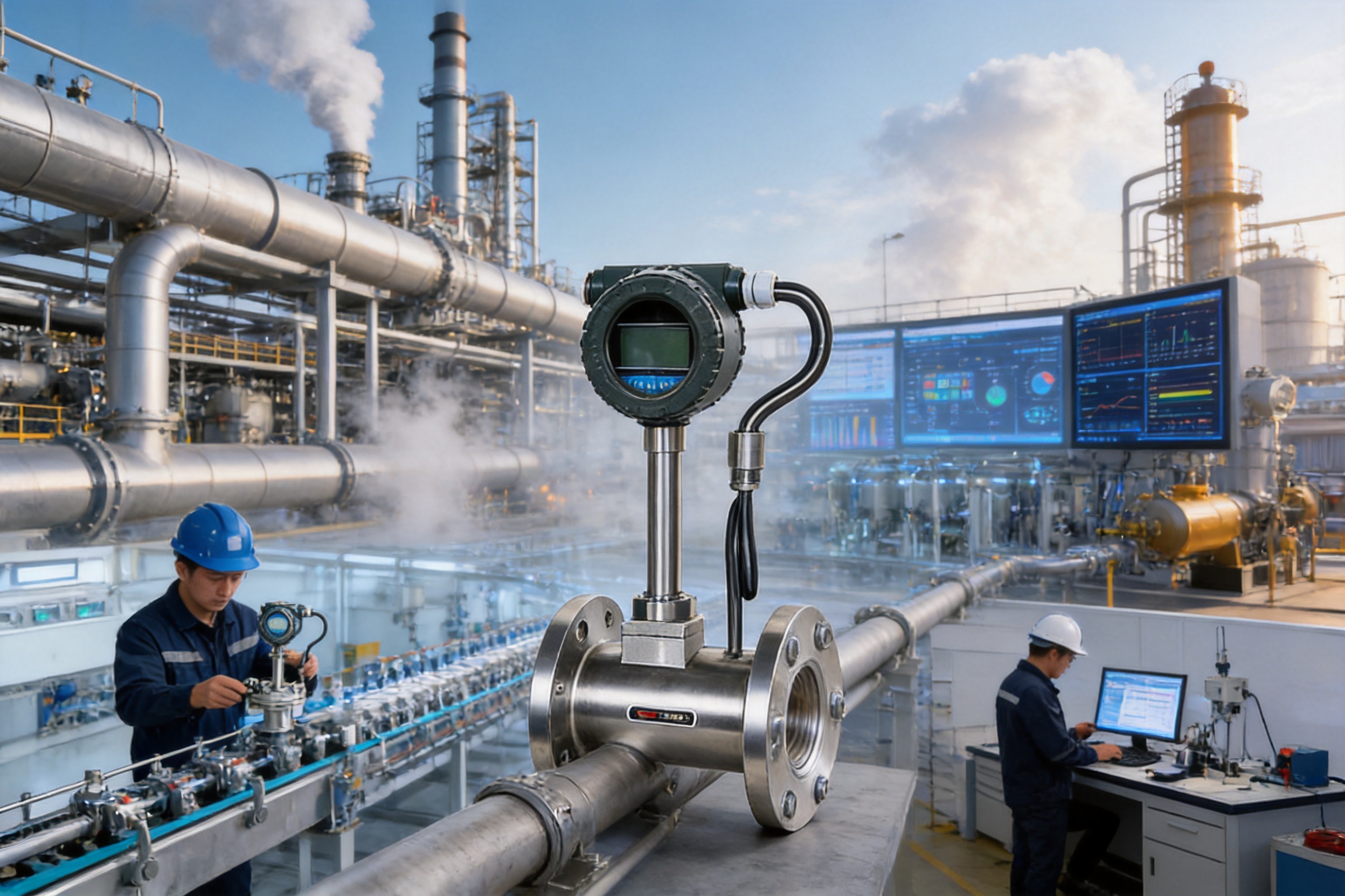
Begin with the medium name and physical state. Specify whether the application involves water, another liquid, compressed air, general gas, saturated steam, or superheated steam. Include density, viscosity, composition, corrosivity, solid content, and scaling tendency when available.
Provide the minimum, normal, and maximum flow rates. The nominal pipe size alone is not sufficient for proper selection. If a pipeline is significantly oversized relative to the normal flow, the velocity may be too low for stable vortex formation. If the meter is undersized, pressure loss and maximum-flow limitations may become concerns.
List normal and maximum temperature, normal and maximum pressure, and any pressure fluctuation or surge. Select the appropriate temperature and pressure classes. For steam, identify the pressure and temperature condition so that saturated or superheated operation can be evaluated correctly.
Choose wafer flanged construction for suitable DN25 to DN300 applications. Consider insertion construction for large pipelines from approximately DN300 to DN2000. A high-pressure, submersible, corrosion-proof, or ball-valve insertion structure may be appropriate for special field conditions.
Identify whether the control system requires 4–20 mA, pulse, HART, RS485, or a combination of functions. Determine whether the meter will be battery-powered, externally powered by 24 VDC, or supplied with a dual-power arrangement.
For liquids with stable density, no compensation may be required. For gases and steam, determine whether temperature, pressure, or combined temperature-and-pressure compensation is needed. If the application requires mass flow or standardized flow, the calculation basis should be documented before order placement.
Check whether the meter will be installed indoors, outdoors, underground, in a damp area, or within a hazardous location. The product information states an IP65 protection level and an explosion-proof rating of Exd II BT4 for the applicable configuration. The final certificate and area classification must be checked for the destination project.
Before commissioning, inspect the pipeline for foreign material, welding slag, loose bolts, deposits, and construction debris. Confirm that the meter is installed in the correct flow direction and that the pipe is full under normal operation.
Check flange alignment, gasket position, bolt tightening, sensor orientation, cable connections, grounding, and enclosure sealing. Confirm that the upstream and downstream straight lengths meet the installation requirements. Verify that the pipe supports do not impose stress on the meter body.
After power is applied, confirm the displayed engineering units, pipe diameter, medium type, compensation parameters, output settings, communication address, and accumulated-flow settings. Compare the local display with the control-system value and verify the direction and scaling of each output.
During operation, observe whether the flow reading is stable at several flow rates. If the value fluctuates, investigate low velocity, pipeline vibration, insufficient straight pipe, bubbles, two-phase flow, valve turbulence, grounding, signal interference, and incorrect parameter settings.
Routine maintenance should include visual inspection, checking for leakage, examining cable glands, verifying enclosure integrity, reviewing diagnostic information, and comparing readings with an independent reference where appropriate. The absence of moving parts reduces mechanical maintenance but does not eliminate the need for installation inspection and periodic verification.
Low pipeline flow is one possible cause of unstable readings. If the flow velocity is below the stable operating range, the vortex signal may be weak or irregular. The solution may involve selecting a more suitable meter diameter, changing the measurement location, or confirming whether the actual flow is lower than the original process estimate.
Large pipeline vibration can introduce interference into the detected signal. Pumps, valves, compressors, and unsupported pipe sections should be checked. Improving pipe support and moving the meter away from vibration sources may resolve the issue.
Insufficient upstream and downstream straight pipe can cause an uneven flow profile. Bends, reducers, valves, and pump bodies should be located as far as practical from the meter. If the existing layout cannot be changed, the manufacturer should review the installation arrangement.
Bubbles in liquid media can cause significant variation. The system should be checked for air ingress, low-pressure flashing, poor pump suction conditions, and inappropriate meter location. A full pipe and stable single-phase flow are important for reliable measurement.
Scaling, solid particles, heavy contamination, and excessive viscosity can interfere with the sensor and distort the flow pattern. Process filtration, cleaning, or a different measurement technology may be required in these cases.
The flowmeter can measure general liquids, gases, saturated steam, and superheated steam when the application meets the instrument’s operating requirements. It is not recommended for media containing large amounts of solid particles or for highly viscous media that readily form scale, because these conditions can damage the probe or affect vortex formation and measurement stability.
The vortex signal is directly related to volumetric flow. Steam mass-flow calculation requires density information based on pressure and temperature. The product supports temperature compensation, pressure compensation, and combined temperature-and-pressure compensation options. The required configuration should be selected according to whether the application needs actual volume, standard volume, or mass flow.
As a general guideline, provide approximately 15 to 20 pipe diameters upstream and approximately 5 to 10 pipe diameters downstream. The final requirement depends on the nearby fittings and the installation standard. Bends, valves, pumps, reducers, expanders, and other turbulence sources should be kept away from the meter as far as practical.
Common causes include flow below the minimum operating range, pipeline vibration, insufficient straight pipe, bubbles in liquid, two-phase flow, unstable pressure, incorrect parameter settings, poor grounding, and nearby turbulence-producing equipment. The process and installation should be checked systematically rather than assuming that the sensor is defective.
A vortex flowmeter is suitable for steam, gases, and non-conductive liquids. An electromagnetic flowmeter is generally selected for conductive liquids such as wastewater, acid, alkali, and mud. The key selection factor is the physical and electrical nature of the measured medium.
Wafer flanged versions are listed from DN25 to DN300. Insertion versions extend from approximately DN300 to DN2000. Insertion flow ranges are based on the flow velocity at the insertion center point, so the final selection should consider pipe diameter, velocity profile, and the actual process flow.
Yes. The product family includes an internal-battery configuration, a battery plus external 24 V dual-supply configuration, and a 24 VDC-only configuration. The available output functions and battery performance depend on the selected electronics and operating conditions.
Available options include 4–20 mA, pulse, HART, and RS485 communication. The exact combination should be specified during ordering so that it matches the receiving PLC, DCS, SCADA, or energy-management system.
The product information lists an explosion-proof rating of Exd II BT4 for the applicable configuration. Users must confirm the actual certificate, area classification, temperature class, installation method, cable-gland requirements, and local regulatory requirements before installation in a hazardous area.
The stated housing materials are stainless steel and carbon steel. The preferred material depends on the surrounding environment, process conditions, corrosion risk, mechanical requirements, and project specifications.
Yes. Depending on the selected configuration and programmed parameters, the LCD can display temperature, pressure, instantaneous flow, cumulative flow, density, and frequency. This provides useful information for commissioning and field inspection.
Provide the medium, minimum and maximum flow, normal flow, pipe diameter, operating temperature, operating pressure, required accuracy, installation structure, output type, compensation requirement, power supply, environment classification, housing material, and any special certification or documentation requirements.
The XG-LUGB series intelligent vortex flowmeter combines a simple mechanical structure with digital signal processing and flexible communication. Its ability to measure liquids, gases, and steam gives it broad usefulness across industrial utility and process systems. Its low pressure-loss design can support energy-conscious operation, while its lack of traditional moving parts can reduce maintenance requirements.
The product’s intelligent functions add value beyond basic flow indication. Local display, cumulative flow, temperature and pressure parameters, password-protected configuration, data storage, 4–20 mA output, pulse output, HART, and RS485 communication allow the meter to participate in modern plant-control and energy-management systems.
The available wafer and insertion structures cover both small and large pipelines. Normal-pressure, high-pressure, submersible, corrosion-proof, and explosion-proof-related configurations provide additional flexibility for difficult installation environments. Proper model selection remains essential, particularly for low-flow conditions, high-temperature steam, high-pressure lines, corrosive media, and hazardous locations.
The manufacturer’s long operating history, broad instrumentation portfolio, research and development personnel, modern production equipment, inspection procedures, and quality-management certifications provide an important foundation for product consistency and technical support. Its related capabilities in temperature instruments, pressure instruments, alloy materials, cables, and electrical accessories can also support complete measurement-system requirements.
For industrial users seeking one flowmeter family for steam, gas, water, and general process-liquid measurement, the XG-LUGB series offers a practical combination of application range, intelligent functionality, low maintenance, and configuration flexibility. The best results will be achieved when the instrument is selected from actual process data and installed with proper straight-pipe, vibration-control, temperature, pressure, and communication considerations.
1. Product technical information for the XG-LUGB series intelligent vortex flowmeter, including operating principle, features, application industries, configuration options, and flow-range data.
2. Manufacturer information concerning quality management, environmental management, occupational health and safety management, research and development, manufacturing capability, and industrial instrumentation production.
3. General engineering references on Karman vortex shedding, vortex frequency, Strouhal number, flow velocity, and industrial vortex-flow measurement.
4. General industrial guidance for flowmeter installation, upstream and downstream straight-pipe requirements, pipeline vibration control, and process-flow conditioning.
5. General reference materials concerning steam flow measurement, pressure and temperature compensation, density calculation, and mass-flow estimation.
6. General reference materials concerning 4–20 mA signaling, pulse outputs, HART communication, RS485 networks, and Modbus-based industrial integration.
7. General quality-management and instrumentation documentation relating to ISO9001, ISO14001, GB/T28001, IEC requirements, and hazardous-area equipment selection.



 INQUIRY
 English
 عربى
 русский
 中文简体