Industrial pressure measurement becomes increasingly demanding as process media become more corrosive, viscous, abrasive, crystallizing, or contaminated with suspended solids. In many applications, a conventional pressure gauge cannot provide dependable service because the measured medium enters the pressure-sensing system and directly contacts the spring tube, movement, and other sensitive components. Corrosion, clogging, crystallization, pointer sticking, and movement damage may then lead to inaccurate readings, premature failure, unplanned maintenance, and potential safety risks.
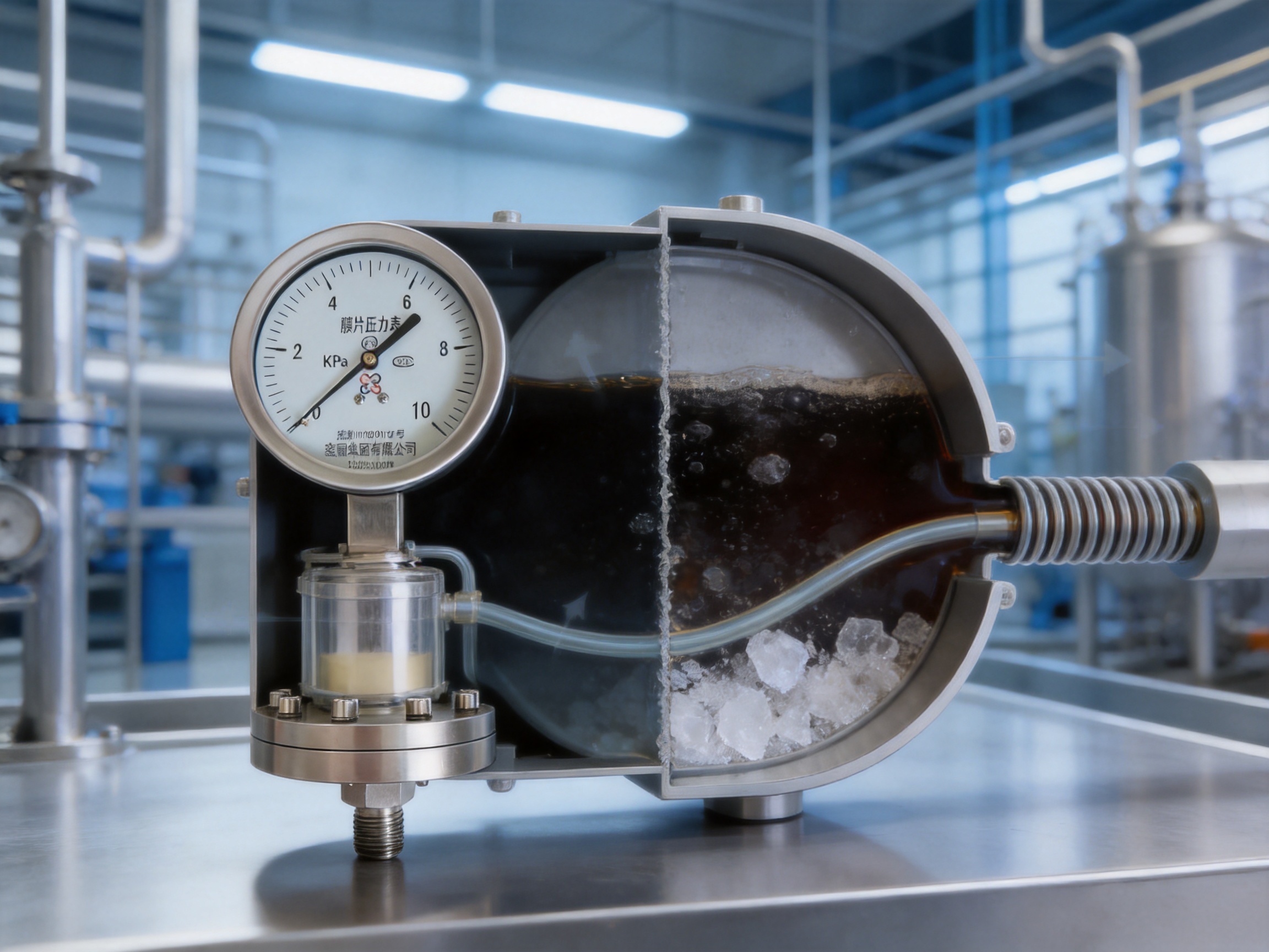
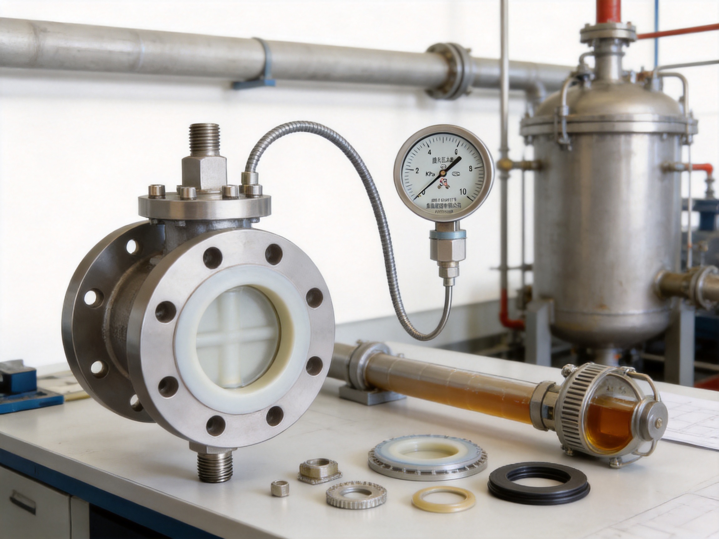
The XG/Y-M series diaphragm pressure gauge is designed for these difficult operating conditions. It is an indirect pressure-measuring instrument consisting of a pressure gauge head and a diaphragm isolator. The process medium contacts only the isolation diaphragm and the connected flange or joint. It does not enter the internal mechanism of the gauge head. Pressure is transferred through a sealed filling fluid from the diaphragm to the spring tube, allowing the instrument to display local pressure while maintaining physical separation between the process medium and the movement.
This construction gives the XG/Y-M series a significant advantage over ordinary stainless steel pressure gauges in applications involving strong chemicals, high-viscosity liquids, slurries, crystalline substances, powders, and media containing solid particles. It also allows engineers to select diaphragm, flange, gasket, and filling-fluid materials according to the process conditions rather than relying on one standard material for every application.
A pressure gauge must transmit process pressure to its sensing element while protecting its internal mechanism from the process environment. In a standard pressure gauge, the medium commonly enters the pressure connection and acts directly on the spring tube. This arrangement can work effectively when the medium is clean, noncorrosive, and sufficiently fluid. However, the same design becomes vulnerable when the medium can attack, block, solidify, or contaminate the pressure-sensing path.
A diaphragm pressure gauge introduces a flexible membrane between the process medium and the measuring mechanism. When the process pressure changes, the diaphragm deflects. This movement acts on the sealed pressure-transmission fluid inside the isolator. The fluid then transfers the pressure to the spring tube in the gauge head, and the spring tube movement is converted into pointer movement on the dial.
The process medium therefore remains confined to the wetted side of the diaphragm and the process connection. The pressure gauge head remains protected from direct exposure. This principle is particularly valuable where even a small quantity of process contamination could affect the accuracy or reliability of the instrument.
The isolation system also reduces the possibility of hazardous process media leaking into the gauge movement. While correct installation, material selection, and preventive maintenance remain essential, the diaphragm structure provides an additional protective barrier between the process and the operator-facing instrument mechanism.
The most important structural feature of the XG/Y-M series is complete separation between the process medium and the internal movement. The diaphragm, flange or joint, and selected sealing components form the wetted boundary. The spring tube, gear movement, pointer, dial, and other internal parts are not directly exposed to the medium.
This separation prevents corrosive media from attacking the spring tube or movement. It also prevents viscous liquids from entering and solidifying inside the pressure passage. When the medium contains crystals or particles, the diaphragm acts as a flexible barrier rather than allowing those materials to accumulate in a narrow internal channel.
Compared with a standard gauge, the diaphragm design can significantly reduce the number of failure mechanisms associated with process contamination. It does not eliminate all possible failures, because the diaphragm itself must still be correctly selected for pressure, temperature, and chemical compatibility. Nevertheless, it moves the sensitive measurement mechanism away from the most aggressive part of the process.
Indirect pressure transmission is achieved through the sealed liquid filling inside the diaphragm isolator. The filling liquid must remain stable over the specified pressure and temperature range. Its viscosity, density, expansion coefficient, and chemical stability influence measurement behavior.
When pressure is applied to the diaphragm, the membrane transfers the force to the filling liquid. The filling liquid then applies pressure to the spring tube of the gauge head. Because the transmission path is sealed, the system can remain clean and protected from external contamination. The result is a stable pressure signal suitable for local indication in many industrial processes.
The transmission fluid also allows the gauge head to be used with different diaphragm materials and process connection designs. By combining suitable materials and filling liquids, the same basic gauge concept can be adapted to chemical, food-grade, high-temperature, oxygen, hydrogen, and other specialized services.
The XG/Y-M series diaphragm pressure gauge consists of several coordinated components. Each component contributes to measurement performance, corrosion resistance, mechanical protection, or installation flexibility.
| Component | Primary Function | Selection Considerations |
|---|---|---|
| Diaphragm membrane | Separates the process medium from the gauge head and senses pressure | Process chemistry, temperature, pressure range, permeability, and corrosion resistance |
| Flange or process joint | Connects the gauge to the tank, pipe, or process equipment | Connection standard, pressure rating, wetted material, and installation space |
| Sealing gasket | Maintains a tight boundary between the gauge and process connection | Temperature, chemical compatibility, compression, and service life |
| Pressure-transmission liquid | Transfers diaphragm movement to the spring tube | Temperature range, specific gravity, expansion coefficient, viscosity, and application safety |
| Gauge head | Converts spring tube movement into local pressure indication | Accuracy, vibration level, enclosure type, shock resistance, and optional electrical contacts |
| Pointer and dial | Provide direct visual pressure indication | Scale range, units, readability, and required installation orientation |
The diaphragm is engineered to deflect in response to pressure while maintaining a reliable seal. Its geometry and material influence sensitivity, pressure range, response speed, and resistance to fatigue. A properly selected diaphragm can provide repeatable pressure transmission without allowing the process medium to reach the gauge movement.
Diaphragm construction is especially useful for media that cannot pass through a small internal pressure channel. High-viscosity substances may flow slowly or not at all through conventional connections. Crystallizing substances can form deposits as temperature changes or solvent evaporates. Solid particles can lodge in restricted passages. The diaphragm arrangement minimizes these internal obstructions because the process side can be designed with a more open, flush, or application-specific interface.
The gauge head uses a spring tube to convert transmitted pressure into mechanical movement. As pressure enters the spring tube, its curved form tends to straighten or change shape. A mechanical movement connected to the spring tube transfers this displacement to the pointer.
Because the spring tube is exposed only to the sealed transmission liquid, it is protected from direct process corrosion and contamination. The spring tube and movement can therefore be manufactured and calibrated for stable mechanical performance without requiring direct compatibility with every process chemical.
The standard instrument provides local pressure indication through a dial and pointer. Depending on the application, the gauge head can be combined with an ordinary configuration, an oil-filled configuration, a shock-resistant configuration, an electric-contact configuration, or an all-stainless-steel body.
An oil-filled gauge head is useful where the installation is subject to vibration, pulsation, or mechanical shock. The filling dampens pointer oscillation and reduces the effect of rapid movement on the internal mechanism. Electric-contact versions can support alarm or control functions when the process pressure reaches a preset value. These options allow one diaphragm gauge platform to support measurement, monitoring, and basic pressure alarm requirements.
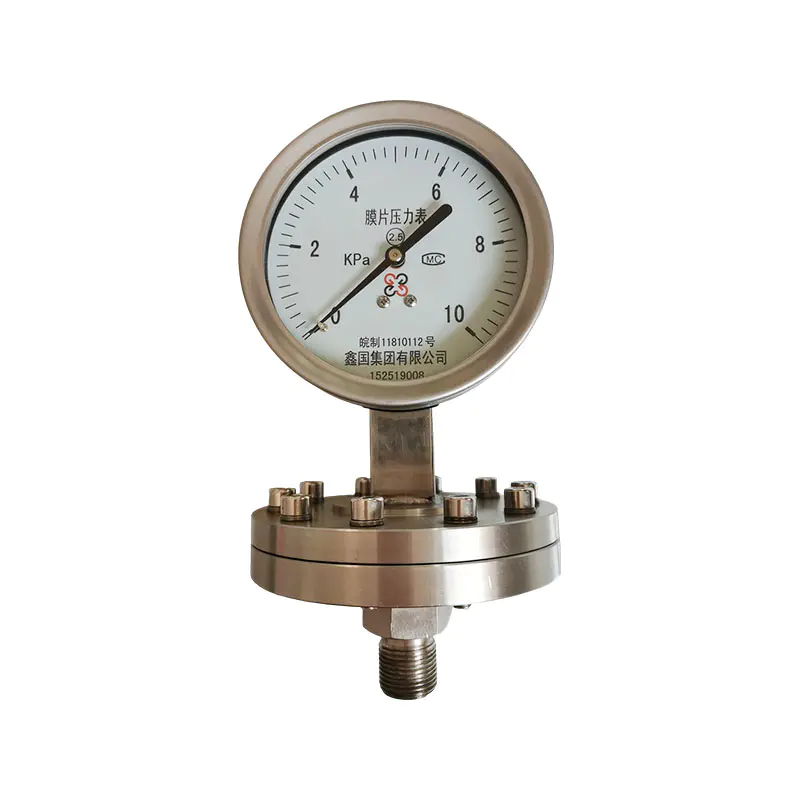
XG/Y-M series diaphragm pressure gauge
Corrosion is one of the most common reasons for premature pressure gauge failure. In an ordinary gauge, the process medium may directly contact the spring tube and other pressure-bearing components. Even when the exterior housing is made of stainless steel, the internal wetted parts may not be suitable for every chemical.
The diaphragm pressure gauge reduces this exposure by limiting contact to the selected wetted materials. A 316L diaphragm may be suitable for many moderate corrosion conditions. Hastelloy can be selected for more aggressive chemical environments. Monel, tantalum, or fluoroplastic-lined designs may be considered for specialized media when their chemical compatibility has been confirmed.
This approach provides a practical advantage over using a standard gauge with a general-purpose stainless steel pressure connection. Instead of allowing the entire pressure mechanism to face the process, the engineer can focus material selection on the diaphragm, flange, gasket, and other wetted parts.
Clogging can make a pressure gauge slow to respond, inaccurate, or completely unusable. The risk is high when the process contains suspended solids, fibers, crystals, pigments, sludge, or viscous compounds. A narrow pressure channel may become restricted even if the gauge was initially suitable for the application.
The diaphragm forms a broad sensing boundary that does not require the process medium to travel deeply into the gauge head. This reduces the likelihood that solid particles will penetrate the mechanism or that crystals will accumulate in the internal movement. As a result, the instrument is less likely to experience pointer jamming or blocked pressure transmission caused by process deposits.
For particularly difficult services, the process connection and diaphragm interface should still be selected carefully. Flush diaphragm arrangements, suitable flange designs, and appropriate cleaning procedures may further improve reliability. The diaphragm principle provides the foundation, but the complete installation must be designed for the physical behavior of the medium.
High-viscosity media can be difficult to measure with conventional pressure gauges because the substance may not respond quickly in a narrow passage. It may also remain inside the connection and gradually change consistency as temperature varies.
The XG/Y-M series keeps the viscous medium away from the spring tube and internal movement. Pressure acts on the diaphragm, and the sealed transmission fluid carries the signal to the gauge head. This arrangement is suitable for many viscous liquids, slurries, pastes, and process mixtures that would otherwise cause delayed response or blockage.
The operating temperature of the process remains important. A viscous medium may become more mobile at higher temperature and more solid at lower temperature. Engineers should consider startup conditions, shutdown conditions, cleaning cycles, and possible solidification when selecting the diaphragm design and installation position.
Particles can damage pressure-sensing components through abrasion or can become trapped in the pressure path. In processes such as mineral handling, chemical production, wastewater treatment, pigment manufacturing, and slurry transport, particle size and concentration may vary continuously.
By placing the diaphragm between the process and the gauge movement, the instrument reduces the chance that particles will reach the spring tube. The diaphragm must still be selected for mechanical strength and wear conditions, but the movement is protected from direct particle impact. This can extend service life and reduce the frequency of cleaning and replacement.
The availability of multiple diaphragm materials is a major benefit in chemical applications. Selecting a material based on the actual process composition is more dependable than selecting a gauge only by nominal pressure range or external housing material.
316L stainless steel is commonly used for general industrial service and many mildly corrosive media. Hastelloy alloys offer improved resistance in selected strong acid, alkaline, and chemical applications. Monel may be suitable for certain environments involving nickel-copper compatibility requirements. Tantalum can be considered for highly aggressive chemical conditions where its compatibility is appropriate. Fluoroplastic materials such as PTFE can provide a useful barrier in applications requiring resistance to a broad range of chemicals.
Material selection must be based on the complete process, including concentration, temperature, pressure, impurities, residence time, cleaning chemicals, and possible chemical combinations. No single material is universally resistant to every substance. The advantage of the diaphragm gauge is that it provides a structured way to tailor the wetted boundary to the application.
The materials that contact the process medium determine the long-term resistance of the instrument. The diaphragm, flange, gasket, and any lining must be considered as one system. Choosing a corrosion-resistant diaphragm while overlooking the gasket or flange may still result in leakage or early deterioration.
316L stainless steel is a widely used diaphragm material for many industrial applications. It offers good general corrosion resistance, mechanical strength, and availability. It is often selected for water treatment, general chemical processing, food-related systems, and moderate corrosive service.
Its suitability depends on the exact medium. Chloride concentration, acid content, temperature, and contamination can significantly affect performance. Users should not assume that 316L is appropriate simply because the process is classified as “stainless-steel compatible.” Detailed chemical information should be reviewed before final selection.
Hastelloy alloys are used where stronger corrosion resistance is required. They may be considered for aggressive acid and alkaline solutions, chemical reaction processes, and media in which ordinary stainless steel could suffer rapid attack.
The correct Hastelloy grade should be confirmed according to the medium and service temperature. Chemical composition, concentration, oxidizing conditions, and impurities can influence the result. The selection should be made with technical input from the instrument supplier and, where necessary, a materials specialist.
Monel alloys can be useful in selected applications involving seawater, alkalis, and other chemical environments where nickel-copper alloys provide appropriate resistance. Tantalum offers excellent resistance in certain severe chemical services, although its mechanical and economic characteristics must also be considered.
These materials are not interchangeable. Each has specific strengths and limitations. The decision should account for pressure, temperature, mechanical loading, chemical concentration, and cost. The diaphragm gauge platform makes these options available for applications where ordinary stainless steel would be insufficient.
Fluoroplastic materials, including PTFE, are valued for their broad chemical resistance and low tendency to adhere to many process substances. A fluoroplastic-lined flange or diaphragm structure can be suitable for strongly corrosive media or media with a high risk of chemical attack.
Temperature, mechanical pressure, permeability, and deformation must be considered when using fluoroplastic components. PTFE may behave differently from metallic diaphragms under pressure and temperature cycling. The design should therefore be selected according to the manufacturer’s application limits rather than relying only on chemical resistance tables.
Common gasket choices include nitrile rubber, fluororubber, silicone rubber, and fluoroplastic materials. Nitrile rubber may be suitable for general industrial fluids, while fluororubber can provide improved resistance to selected oils, fuels, and chemicals. Silicone rubber is often chosen for temperature flexibility and certain food or general-purpose applications. Fluoroplastic gaskets are used where chemical resistance is a priority.
The gasket must maintain compression without excessive swelling, hardening, cracking, or permeation. Temperature cycling and bolt loading should also be considered. A correct diaphragm material cannot compensate for a gasket that is incompatible with the process.
The diaphragm system is filled with a sealing liquid that transfers pressure from the membrane to the spring tube. This liquid affects the accuracy, temperature behavior, response, and safety of the instrument. The choice should be based on the temperature of the pressure-bearing part, the process environment, and any special requirements related to food, oxygen, hydrogen, or other services.
| Sealing Liquid | Approximate Temperature Range of Pressure-Bearing Part | Specific Gravity | Volume Expansion Coefficient | Typical Application |
|---|---|---|---|---|
| High-viscosity silicone oil | -10 to 200 degrees Celsius | 1.07 grams per cubic centimeter | 0.95 × 10^-3 per degree Celsius | High-temperature service |
| Low-viscosity silicone oil | -30 to 100 degrees Celsius | 0.94 grams per cubic centimeter | 1.08 × 10^-3 per degree Celsius | General service |
| Glycerin aqueous solution | -5 to 100 degrees Celsius | 1.27 grams per cubic centimeter | 0.61 × 10^-3 per degree Celsius | Food-grade service |
| Vegetable oil | -5 to 100 degrees Celsius | 0.93 grams per cubic centimeter | 1.03 × 10^-3 per degree Celsius | Food-grade service |
| Fluorine oil | -30 to 150 degrees Celsius | 1.93 grams per cubic centimeter | 0.75 × 10^-3 per degree Celsius | Hydrogen and oxygen service |
Temperature affects a diaphragm pressure gauge through several mechanisms. The transmission liquid expands or contracts as temperature changes. The diaphragm stiffness may vary. The pressure-bearing parts may experience thermal deformation. The gauge head itself also has a temperature response similar to that of a general pressure gauge.
For low-range instruments, the temperature effect of the diaphragm system can be particularly noticeable because a small additional pressure caused by liquid expansion may represent a significant portion of the measuring range. The total temperature effect is generally the combined effect of the ordinary gauge mechanism and the diaphragm seal assembly.
The specified temperature error of the pressure-bearing part should be reviewed during instrument selection. A commonly referenced design consideration is that the temperature error of the pressure-bearing part should not exceed approximately 0.1 percent per degree Celsius, subject to the actual product specification and calibration conditions.
High-temperature service may require a heat-dissipation device, cooling element, or remote diaphragm connection. These arrangements reduce the temperature transmitted to the gauge head and help protect the transmission liquid and mechanical movement. The installation should allow sufficient cooling distance and avoid unnecessary heat conduction through the process connection.
High-viscosity silicone oil is appropriate for many high-temperature applications within its specified operating range. Low-viscosity silicone oil is commonly used for general industrial service because it provides suitable pressure transmission over a broad moderate-temperature range.
Glycerin aqueous solution and vegetable oil can be considered for selected food-grade applications, provided that the complete instrument construction and process hygiene requirements are also appropriate. Fluorine oil may be selected for certain hydrogen and oxygen services, where the safety characteristics of the filling liquid are essential.
The filling liquid should never be selected only by temperature range. Chemical safety, oxygen compatibility, hydrogen compatibility, food-contact requirements, density, expansion behavior, and regulatory requirements may all influence the decision.
Industrial equipment varies widely in layout, access, pipe size, vessel design, and maintenance requirements. The XG/Y-M series supports direct, threaded, and flanged installation forms, helping engineers match the gauge to tanks, pipelines, reactors, pumps, and other process equipment.
Direct installation places the gauge close to the pressure tapping point. It provides a compact arrangement and can simplify visual reading when the instrument is accessible to operators. Direct mounting is most suitable when the process temperature, vibration, and ambient conditions are within the limits of the gauge head.
The gauge should be installed in a position that prevents mechanical stress on the connection. The process port should be clean and free from sealing debris. Pipe alignment should not force the gauge into position, because external stress can influence readings or damage the connection.
Threaded connections are convenient for many pipelines and compact equipment. They can be used where the process connection is standardized and the medium does not require a large open diaphragm interface.
Thread sealant must be selected for chemical compatibility and applied carefully. Excess sealant should not enter the process passage or interfere with the diaphragm. The gauge should be tightened using the appropriate connection surface rather than applying torque to the case or pointer mechanism.
Flanged diaphragm gauges are useful for larger pipes, tanks, reactors, and processes involving viscous, solid-containing, or highly corrosive media. Flanges can be selected according to common Chinese, German, Japanese, American, and other applicable standards. Special flange specifications may also be available for project-specific requirements.
Flange selection should include nominal size, pressure rating, facing, bolt arrangement, material, gasket type, and diaphragm exposure. The process engineer should verify that the flange design allows adequate contact with the medium and does not create an unnecessary pocket where solids or crystals can accumulate.
Remote diaphragm devices with flexible capillaries can be used when the local process temperature is too high, the gauge cannot be read directly at the tapping point, or the instrument must be placed at a more convenient operating location. This arrangement separates the pressure-bearing diaphragm from the gauge head while maintaining hydraulic pressure transmission.
Capillary routing must be planned carefully. Sharp bends, crushing, excessive vibration, and large elevation differences can influence performance. The capillary should be protected from mechanical damage and supported without creating excessive stress.
When the diaphragm and gauge head are installed at different elevations, the pressure-transmission liquid creates a hydrostatic liquid-level difference effect. This effect must be considered when accurate measurement is required, particularly with flexible capillary connections.
The pressure offset can be expressed as:
ΔP = d × h
In this relationship, ΔP is the pressure difference caused by the elevation change, d is the specific gravity of the sealing liquid, and h is the liquid-level difference. The actual sign and correction depend on whether the gauge head is installed above or below the diaphragm.
The effect becomes more significant when the measured pressure is low, the capillary is long, or the elevation difference is large. During project design, the installation height should be documented and the instrument can be calibrated or ranged with the expected hydrostatic offset in mind.
Temperature changes may also influence the liquid-level effect because the density and volume of the transmission liquid can change. For critical low-pressure measurement, the designer should evaluate elevation, temperature, filling liquid, capillary length, and required accuracy together.
Pumps, compressors, reciprocating machinery, valves, and rapidly changing processes can produce vibration and pressure pulsation. These conditions may cause a pointer to oscillate, make the reading difficult to interpret, and accelerate wear in the movement.
An oil-filled or shock-resistant gauge head is recommended for such environments. The filling fluid inside the gauge head damps mechanical movement and reduces pointer fluctuations. It can also help protect the gear movement from vibration-related wear and reduce the chance of the pointer striking the stop repeatedly.
The diaphragm itself must also be protected from pressure shocks. Rapid valve closure, pump startup, water hammer, and process surges can create pressure levels far above normal operating pressure. A gauge should be selected with a suitable range and overpressure capability. If necessary, a pulsation dampener, snubber, pressure-limiting device, or isolation valve should be included in the installation.
Oil filling is not a substitute for correct pressure-range selection. A gauge that is repeatedly subjected to overpressure may suffer diaphragm deformation, spring tube damage, pointer displacement, or loss of calibration even if it is oil-filled and shock-resistant.
Some pressure measurement applications require more than visual indication. Operators may need a signal when pressure reaches a high or low limit, when a pump loses discharge pressure, or when a process vessel approaches a defined operating threshold.
The XG/Y-M series can be paired with electric-contact gauge heads for basic alarm and control functions. The contact mechanism can be configured to respond to pointer position and provide an electrical switching signal. This allows the diaphragm gauge to support local pressure display and limit monitoring in one instrument assembly.
Electrical contact selection should consider contact rating, switching frequency, enclosure requirements, ambient temperature, hazardous-area regulations, and the control system interface. The process isolation function remains the same: the medium is separated from the gauge movement by the diaphragm and sealed transmission system.
For critical control loops or fast pressure regulation, a pressure transmitter may be more appropriate than a mechanical electric-contact gauge. However, for local alarm functions, equipment protection, and straightforward limit indication, an electric-contact diaphragm gauge can offer a practical and economical solution.
The performance of a diaphragm pressure gauge depends not only on its design but also on the consistency of manufacturing. Diaphragm forming, welding or sealing, filling, calibration, cleaning, and final inspection must be controlled carefully because the pressure-transmission system is sealed and cannot be adjusted casually after installation.
Xinguo Group Co., Ltd. is an industrial manufacturer with experience across temperature instruments, pressure instruments, flow meters, level instruments, alloy materials, cables, and related instrumentation products. Its broader manufacturing structure supports coordinated knowledge of materials, mechanical production, pressure measurement, and industrial process requirements.
The group was established in 1997 and operates from Tianchang City in Anhui Province, China. It has a registered capital of RMB 118 million, a land area of more than 150 mu, a construction area of approximately 60,000 square meters, and nearly 300 employees, including more than 50 professional technicians and engineering personnel.
This organizational scale provides several advantages for diaphragm pressure gauge production. Material selection can be supported by internal technical experience. Production can be coordinated across instrument assemblies and metal components. Quality procedures can be applied from incoming materials through machining, assembly, calibration, and final inspection.
A diaphragm gauge must be adapted to different process media, connection standards, temperature ranges, filling liquids, and installation conditions. Engineering capability is therefore essential. A manufacturer with experience in several instrument categories can evaluate the relationship between pressure measurement, materials, temperature, and mechanical construction more effectively than a supplier focused only on a basic gauge design.
The group maintains research and development capabilities supported by professional technicians, senior technical experts, senior engineers, engineers, and assistant engineers. This technical structure supports product improvement, customized connection designs, application consultation, and adaptation to industry-specific requirements.
Consistent diaphragm gauge quality requires controlled forming, precise component assembly, reliable sealing, clean filling, and accurate calibration. Advanced production equipment helps reduce variation between instruments and supports repeatable manufacturing of different sizes and configurations.
Modern manufacturing procedures are particularly important for the sealed transmission system. Air bubbles, contamination, insufficient filling, or leakage can affect pressure response and accuracy. A disciplined production process should include controlled filling conditions, inspection of sealing integrity, and verification of pointer response over the specified range.
The combination of suitable equipment and documented production procedures supports stable output for standard products as well as customized orders. It also makes it easier to trace materials and process parameters when a project requires special diaphragm, flange, gasket, or filling-liquid specifications.
Inspection should cover the raw materials, pressure-bearing components, connections, sealing surfaces, gauge movement, dial, pointer, and finished assembly. Calibration verifies that the displayed pressure corresponds to the applied reference pressure under defined conditions.
For diaphragm gauges, calibration may need to consider the selected filling liquid, diaphragm configuration, connection orientation, temperature, and any elevation-related offset. The manufacturer’s inspection system should be capable of identifying leakage, zero shift, hysteresis, pointer friction, nonlinearity, and insufficient repeatability.
Xinguo Group applies strict inspection procedures at different stages of manufacturing. Its quality management approach is supported by ISO 9001 certification, while environmental management and occupational health and safety systems are supported by ISO 14001 and GB/T 28001 certifications. These systems indicate an organized approach to production management, documentation, process control, and continual improvement.
Industrial users often require products that conform to recognized international, national, and industry specifications. Xinguo Group states that its products comply with IEC international standards as well as applicable national and industrial specifications.
For a diaphragm pressure gauge project, compliance should be confirmed according to the specific product configuration and destination market. Relevant requirements may include pressure gauge standards, flange standards, materials documentation, electrical contact requirements, environmental conditions, hazardous-area regulations, and customer inspection procedures.
A responsible procurement process should request the applicable technical datasheet, calibration information, material details, connection drawings, and inspection documentation. Product conformity is most reliable when the required standards are identified before quotation and incorporated into the technical agreement.
The XG/Y-M series is suitable for many industrial environments in which ordinary pressure gauges have difficulty maintaining reliable service.
Chemical plants handle acids, alkalis, solvents, reaction mixtures, polymers, catalysts, and corrosive process fluids. The diaphragm gauge helps isolate these substances from the pressure movement while allowing the wetted materials to be selected according to chemical compatibility.
In petrochemical systems, viscous hydrocarbons, additives, contaminated liquids, and temperature-sensitive compounds may require a protected pressure-sensing interface. The choice of diaphragm, gasket, filling liquid, and remote installation arrangement should be based on the actual process conditions.
Food, beverage, pharmaceutical, and biotechnology processes may require hygienic materials, cleanable connections, and filling liquids compatible with the application. Glycerin aqueous solutions or vegetable oil may be considered for selected food-grade services, subject to the complete equipment specification.
The gauge connection should be designed to reduce dead spaces and support cleaning procedures where hygiene is critical. The diaphragm surface, gasket, flange, and finish should be evaluated together. A standard industrial design should not automatically be assumed suitable for a hygienic process.
Wastewater, sludge, and treatment chemicals may contain solids, fibers, suspended particles, and corrosive substances. These materials can block conventional pressure connections or damage exposed gauge mechanisms.
A diaphragm pressure gauge can provide better separation from the contaminated medium. Flanged or application-specific connections may be selected for larger pipelines and vessels. Maintenance teams should still establish procedures for cleaning the diaphragm surface and checking for buildup.
Pulp suspensions, paper chemicals, mineral slurries, and abrasive mixtures are often difficult to measure with small internal pressure channels. The diaphragm arrangement reduces the likelihood of particles entering the gauge head and can improve reliability when paired with a suitable process connection.
Abrasive service requires careful attention to diaphragm thickness, flow velocity, solids concentration, and installation orientation. The instrument should not be placed where high-velocity particles continuously impact the sensing membrane unless the design has been selected for that condition.
Pumps and compressors produce pulsation, vibration, and rapid pressure changes. The diaphragm gauge can be combined with an oil-filled or shock-resistant gauge head to improve readability and mechanical durability.
Pressure snubbers, isolation valves, pulsation dampeners, and suitable mounting supports may further improve performance. The gauge range should be selected so normal operating pressure falls within a stable central portion of the scale rather than near the maximum indication.
Correct selection begins with a complete description of the process. The following information should be gathered before ordering a diaphragm pressure gauge.
First, identify the process medium and its complete chemical composition. A general name such as “acid,” “slurry,” or “solvent” may not be sufficient. Concentration, impurities, additives, dissolved gases, and cleaning agents can change material compatibility.
Second, determine the normal operating pressure, maximum working pressure, possible surge pressure, vacuum conditions, and required measuring range. The selected range should provide sufficient margin without sacrificing resolution at normal operating pressure.
Third, record the minimum, normal, maximum, startup, shutdown, and cleaning temperatures. The temperature at the diaphragm may differ from the ambient temperature at the gauge head. If the process is hot, consider a heat-dissipation device, remote diaphragm, or capillary connection.
Fourth, evaluate vibration, pulsation, mechanical shock, and pressure cycling. Select an oil-filled or shock-resistant gauge head when needed. If pressure surges are severe, address the source of the surge rather than relying solely on the gauge.
Fifth, select the diaphragm, flange, gasket, and filling liquid together. These components must be compatible with the medium, temperature, pressure, and hygiene or safety requirements.
Sixth, confirm the connection standard and installation location. Determine whether direct, threaded, flanged, or remote installation is best. Check access for visual reading, maintenance, calibration, and replacement.
Seventh, decide whether an electric contact or other accessory is required. If the gauge will be installed in a hazardous area, electrical and enclosure requirements must be reviewed before selection.
Install the gauge where it can be read safely and maintained without exposing personnel to unnecessary process hazards. Use suitable isolation valves so the instrument can be removed or inspected without shutting down the entire plant whenever practical.
Ensure that the process connection is clean and that no welding slag, metal chips, sealant, or debris can reach the diaphragm. Tighten the connection with the correct tools and avoid applying force to the gauge case, pointer, or capillary.
Provide support for heavy flanged assemblies and remote capillaries. Do not allow the instrument to act as a structural support for unsupported piping. Protect the gauge from direct sunlight, excessive ambient heat, freezing, impact, and corrosive atmospheric exposure where necessary.
Overpressure can permanently deform the diaphragm and produce inaccurate readings or complete failure. The gauge should not be used beyond its specified pressure range. Pressure relief, isolation, and surge control devices should be considered when abnormal pressure is possible.
Do not dismantle the diaphragm area in the field unless the procedure is specifically authorized and supported by the manufacturer. Opening the sealed system can release transmission liquid, introduce air, damage the diaphragm, and compromise calibration.
If the process temperature is high, use a suitable filling liquid and consider a heat-dissipation device. The temperature at the pressure-bearing component should remain within the specified limit. A remote diaphragm or capillary may be needed when the gauge head cannot tolerate the process temperature.
Thermal cycling should also be considered. Repeated heating and cooling can influence zero stability, gasket performance, diaphragm fatigue, and filling-liquid behavior. The gauge should be inspected if the process experiences frequent thermal shocks.
Routine inspection should look for pointer instability, zero shift, leakage, damaged connections, cracked glass, corrosion, capillary damage, and abnormal response. A gauge that suddenly becomes slow or remains at zero may have a blocked process interface, damaged diaphragm, or loss of transmission liquid.
Calibration intervals depend on process severity, regulatory requirements, accuracy needs, pressure cycling, and historical performance. Critical applications should establish a documented calibration and replacement plan rather than waiting for visible failure.

A damaged diaphragm may result from overpressure, corrosion, fatigue, mechanical impact, improper cleaning, or unsuitable material selection. Symptoms can include unstable readings, zero error, loss of response, or leakage of the transmission liquid.
The instrument should be removed from service and inspected by qualified personnel. A damaged diaphragm should not be repaired through unauthorized welding or mechanical reshaping because the original pressure and sealing characteristics may not be restored.
Loss of filling liquid can occur because of diaphragm damage, seal failure, capillary damage, or unauthorized disassembly. It may cause sluggish response, inaccurate readings, or complete loss of pressure transmission.
Do not refill the instrument with an unapproved liquid. The type, viscosity, density, expansion coefficient, cleanliness, and application safety of the original filling liquid must be matched. Factory repair or replacement is normally the safest approach.
Inaccurate readings may be caused by temperature effects, liquid-level differences, pressure pulsation, gauge overload, pointer friction, blocked process surfaces, or calibration drift. Check the installation elevation, operating temperature, pressure range, and vibration conditions before assuming that the movement itself has failed.
For remote capillary systems, verify that the capillary has not been crushed, sharply bent, or exposed to unexpected temperature changes. For low-range gauges, evaluate the effect of the transmission liquid and elevation difference because relatively small hydrostatic offsets can represent a substantial percentage of the reading.
Pointer jamming in a conventional gauge may result from particles, crystals, corrosion products, or viscous process material entering the mechanism. The diaphragm design greatly reduces this risk because the process medium is isolated from the movement.
However, mechanical damage, excessive vibration, movement wear, or external impact can still cause pointer problems. If the pointer does not move smoothly during a controlled pressure test, the gauge should be inspected rather than forced or adjusted in service.
The main value of the XG/Y-M series lies in its ability to solve problems that ordinary pressure gauges cannot solve reliably. It protects the movement from corrosive, viscous, crystalline, and particle-containing media. It provides multiple diaphragm and connection material options. It can be configured for vibration, pulsation, alarm, high-temperature, food-grade, hydrogen, and oxygen-related requirements when the appropriate specifications are selected.
Its indirect measurement principle gives engineers greater freedom to design the wetted boundary around the process rather than exposing the entire pressure movement to the medium. This can reduce corrosion, blockage, pointer jamming, maintenance frequency, and the risk of premature replacement.
The product is also supported by a manufacturer with broad industrial instrumentation capabilities, a substantial production base, technical personnel, quality management systems, and experience in temperature, pressure, flow, level, alloy, cable, and related products. This combination is valuable for projects that require more than a catalog item. It supports technical consultation, customized connections, material coordination, application review, and documentation for industrial procurement.
In competitive comparison, a basic stainless steel pressure gauge may offer a lower initial cost in clean and noncorrosive service. However, that apparent saving can disappear when the gauge requires frequent cleaning, replacement, recalibration, or emergency maintenance. For harsh media, the diaphragm pressure gauge often provides a lower lifecycle cost by protecting the movement and extending instrument service life.
An ordinary stainless steel pressure gauge usually allows the process medium to contact the internal spring tube directly. A diaphragm pressure gauge uses a flexible membrane to separate the medium from the gauge head. Pressure is transmitted through a sealed liquid. This makes the diaphragm design more suitable for strongly corrosive, viscous, crystalline, and particle-containing media.
316L stainless steel is commonly used for moderate corrosion conditions. Hastelloy may be selected for stronger acid, alkaline, or chemical service. Monel, tantalum, and PTFE or other fluoroplastic materials may be considered for specialized environments. The correct choice depends on the complete chemical composition, concentration, temperature, pressure, and exposure time.
Yes, it can be suitable for many slurries and particle-containing media because the process material does not enter the gauge movement. The diaphragm and process connection must still be selected for the particle size, concentration, flow behavior, abrasion, and cleaning requirements.
An oil-filled or shock-resistant gauge head is recommended for locations with vibration, pulsation, pumps, compressors, or mechanical shock. The filling dampens pointer movement and helps protect the internal mechanism. It does not replace correct pressure-range selection or surge protection.
High temperature can affect the diaphragm, transmission liquid, gauge head, gasket, and calibration. A suitable high-temperature filling liquid, heat-dissipation device, cooling element, or remote diaphragm arrangement may be required. The temperature at the pressure-bearing part must remain within the specified product limit.
If the diaphragm and gauge head are installed at different elevations, the filling liquid creates a hydrostatic pressure offset. The effect can be estimated using ΔP = d × h, where d is the specific gravity of the filling liquid and h is the elevation difference. This is especially important for low-pressure and high-accuracy measurements.
Yes, the gauge head can be paired with an electric-contact configuration for pressure alarm or basic control functions. Contact rating, switching requirements, enclosure protection, electrical area classification, and control-system compatibility should be confirmed before ordering.
First isolate the gauge safely and verify that the process pressure is present. Possible causes include a blocked diaphragm interface, diaphragm damage, loss of transmission liquid, movement failure, or external mechanical damage. Do not force the pointer or dismantle the sealed diaphragm area. The instrument should be inspected by qualified service personnel.
The sealed diaphragm area should not be dismantled without authorization. Improper disassembly may cause leakage, introduce air, damage the membrane, and change calibration. Cleaning procedures should be designed around the selected process connection and should follow the manufacturer’s instructions.
Provide the process medium and chemical composition, normal and maximum pressure, pressure range, temperature range, vibration conditions, connection type and standard, installation orientation, diaphragm and flange material requirements, gasket material, filling liquid, gauge head type, electric-contact requirements, and any applicable certification or inspection requirements.
The XG/Y-M series diaphragm pressure gauge provides a reliable method for measuring pressure in process conditions where ordinary pressure gauges are vulnerable to corrosion, clogging, crystallization, particle contamination, and mechanical damage. Its diaphragm isolation structure keeps the process medium away from the internal movement while transferring pressure through a sealed filling liquid to the spring tube.
The product’s main advantages include protection of the gauge mechanism, improved suitability for harsh media, reduced clogging risk, flexible material selection, stable pressure transmission, and multiple installation configurations. With options for 316L, Hastelloy, Monel, tantalum, PTFE, and other wetted materials, the gauge can be adapted to a wide range of chemical and industrial services.
Proper performance depends on complete application engineering. The diaphragm, flange, gasket, filling liquid, pressure range, temperature limit, installation elevation, vibration conditions, and maintenance plan must be selected together. When this work is completed correctly, the instrument can reduce lifecycle costs and improve the reliability of local pressure indication.
Supported by broad manufacturing capabilities, technical personnel, modern equipment, quality management systems, and industrial instrumentation experience, Xinguo Group Co., Ltd. can provide diaphragm pressure gauge solutions for standard and demanding applications. For corrosive, viscous, crystallizing, and particle-containing media, diaphragm isolation is not merely an accessory; it is a fundamental measurement strategy for protecting the instrument and maintaining dependable process information.
1. Industrial Pressure Measurement Principles, reference material on Bourdon tube gauges, diaphragm seals, pressure transmission, and calibration practice.
2. Materials Compatibility for Process Instrumentation, reference guidance on stainless steel, nickel alloys, tantalum, fluoroplastics, elastomers, and chemical service.
3. Technical Guidance for Diaphragm Seals and Remote Pressure Connections, reference material on capillary routing, elevation effects, temperature compensation, and filling liquids.
4. Quality Management Systems for Manufacturing Organizations, ISO 9001 quality management principles.
5. Environmental Management Systems, ISO 14001 environmental management principles.
6. Occupational Health and Safety Management Systems, GB/T 28001 reference requirements.
7. International and Industrial Specifications for Pressure Gauges, pressure instruments, process connections, and mechanical indication systems.



 INQUIRY
 English
 عربى
 русский
 中文简体