Industrial pressure measurement is often required to do much more than display a process value. In many plants, a pressure instrument must also initiate an alarm, stop a pump, start a compressor, protect a vessel, or activate an interlock when pressure moves beyond a defined limit. These requirements become more demanding when the instrument is exposed to corrosive media, mechanical vibration, pulsating pressure, temperature changes, dust, humidity, or viscous and contaminated process fluids.
The XG/YXC series special magnetic-assisted electric contact pressure gauge is designed for precisely these challenging applications. It combines local pressure indication with magnetic-assisted electrical switching in one mechanical instrument. The pressure gauge provides a readable pointer indication, while its adjustable electrical contacts provide switch signals for external control circuits. With stainless-steel construction, corrosion-resistant options, vibration-resistant versions, and diaphragm isolation structures, the series extends the application range of conventional magnetic-assisted electric contact pressure gauges.
This product is manufactured by Xinguo Group Co., Ltd., a Chinese industrial instrumentation and materials manufacturer with capabilities covering temperature instruments, pressure instruments, flow meters, level instruments, alloy wire, cables, and related components. The group’s integrated technical resources, material expertise, modern production facilities, inspection procedures, and quality-management systems support the development of pressure instruments for demanding industrial environments.
The special magnetic-assisted electric contact pressure gauge is a pressure-measuring and control device derived from the ordinary magnetic-assisted electric contact pressure gauge. Its basic function is to measure the pressure of a medium through an elastic sensing element and display the measured value on a dial. At the same time, adjustable magnetic-assisted electrical contacts monitor the pointer position and produce electrical switch signals when pressure reaches preset upper or lower limits.
The product is especially suitable where a pressure transmitter, programmable controller, or separate pressure switch is not necessary for a basic alarm or interlock function. It offers direct local indication and contact output in a single housing. External relays, contactors, control cabinets, pump starters, valve actuators, and other equipment can use the contact signal to complete the required control action.
Unlike a basic pressure gauge intended only for visual monitoring, this instrument can support practical process-control functions. Typical examples include high-pressure alarm, low-pressure alarm, pump start and stop, compressor protection, pressure-limit indication, equipment interlocking, and emergency shutdown initiation through an appropriate external control circuit.
The series is available in several special configurations. These include ammonia-service models, vibration-resistant models, corrosion-resistant models, corrosion-resistant and vibration-resistant combinations, standard diaphragm models, corrosion-resistant diaphragm models, vibration-resistant diaphragm models, and combined corrosion-resistant and vibration-resistant diaphragm models.
Each configuration is intended to address a specific industrial problem. A vibration-resistant version helps reduce pointer instability and contact misoperation in mechanically active installations. A corrosion-resistant version uses appropriate materials for components exposed to the medium or environment. A diaphragm model isolates the internal pressure-measuring mechanism from the process fluid, making it appropriate for viscous, contaminated, corrosive, particle-containing, or otherwise unsuitable media when the correct isolator is selected.
The instrument is therefore not a single-purpose gauge but a configurable product family. The user can select the pressure range, connection arrangement, housing and wetted materials, vibration protection, diaphragm isolation, and other options according to the process conditions.
XG/YXC series special magnetic assisted electric contact pressure gauge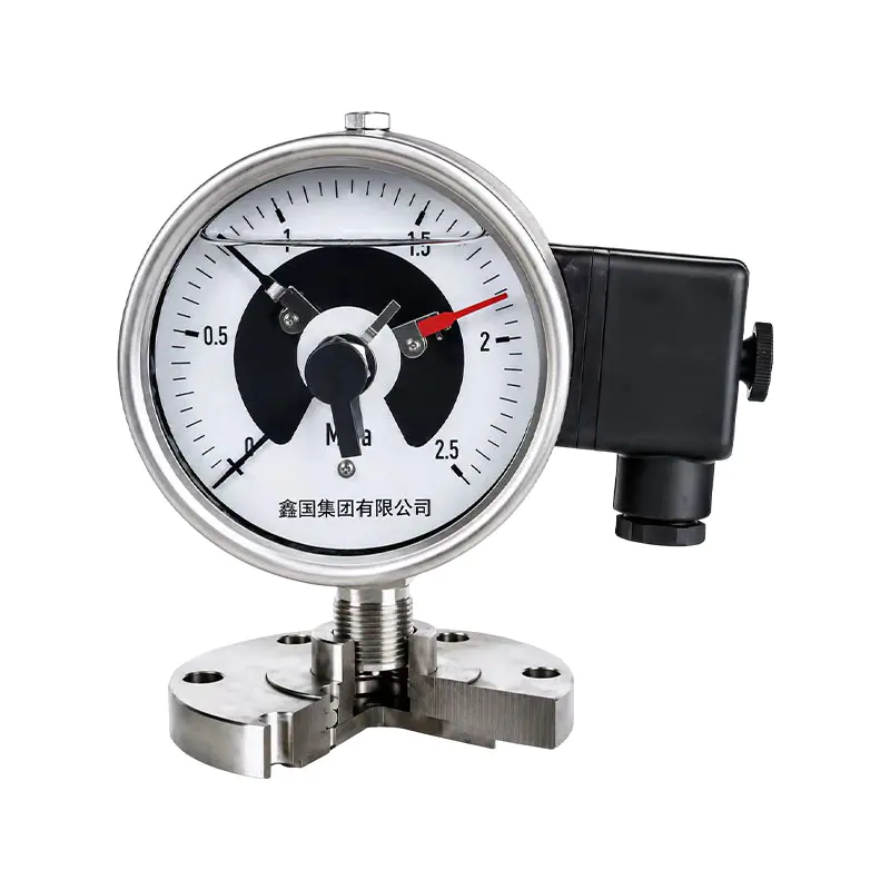
The operating principle is based on the elastic deformation of a pressure-sensitive element. When process pressure enters the pressure connection, it acts on the internal elastic element. Depending on the selected construction, this may be a spring tube or a diaphragm-based pressure-isolation structure. The pressure causes controlled deformation of the elastic element.
A mechanical movement transfers this deformation to the pointer shaft. The pointer then rotates across the graduated dial and provides a local indication of pressure. This mechanical transmission allows the operator to observe the process value without a separate power supply for the indication function.
The magnetic-assisted contact system operates in parallel with the pointer indication. Adjustable contact elements are positioned at selected pressure values. As the pointer approaches a set point, the magnetic structure assists the contact movement. Once the pressure reaches the configured upper or lower limit, the contact rapidly makes or breaks the circuit according to the selected contact arrangement.
Magnetic assistance increases the effective switching force. This helps the contacts move decisively instead of slowly hovering around the switching point. Rapid contact movement can reduce the duration of electrical arcing and help limit contact erosion. It can also improve switching stability when the process pressure contains moderate pulsation or when the instrument is subject to mechanical disturbance.
The contact output is intended to provide a signal rather than directly power a high-load device. The signal can be connected to an external relay, contactor, control module, or other suitable switching component. The external device then handles the current required by a pump, motor, solenoid valve, or other equipment. Directly connecting a high-power load to the pressure-gauge contacts can cause overheating, contact damage, or premature failure.
For applications requiring two control limits, the instrument can be configured for upper-limit and lower-limit functions. A high-pressure contact may initiate an alarm or stop a pump, while a low-pressure contact may start a pump or activate a low-pressure protection circuit. The exact logic depends on the contact arrangement and the external control design.
Ordinary mechanical electrical contacts can be sensitive to pressure movement, vibration, contact bounce, and small variations around a set point. When the pointer oscillates near the switching position, the contact may repeatedly open and close. This can create nuisance alarms, unnecessary relay operation, and accelerated electrical wear.
The special series uses an enhanced magnetic-assisted contact structure intended to provide stronger magnetic torque and more decisive switching. The magnetic force supports rapid contact opening and closing. In practical operation, this helps reduce false triggering, virtual connection, and unstable switching caused by small pointer movements.
The enhanced contact system is particularly valuable in equipment with pulsating pressure. Examples include reciprocating pumps, compressors, hydraulic systems, pressure vessels connected to rapidly cycling processes, and pipelines with periodic flow changes. In these environments, a conventional contact mechanism may be subjected to repeated movement and electrical arcing.
Magnetic assistance does not eliminate the need for correct installation and control-point selection. If the set point is placed within a continuously fluctuating pressure zone, any mechanical contact gauge may experience repeated switching. The correct approach is to evaluate the pressure profile, select an appropriate switching differential and contact arrangement, and use a vibration-resistant or shock-resistant version when necessary.
The product’s enhanced magnetic system is therefore one part of a broader protection strategy. Its benefits are strongest when combined with correct pressure-range selection, suitable mechanical installation, proper electrical protection, and regular inspection of the contacts and zero point.
The special magnetic-assisted contact system increases the force available during switching. This helps the contacts open and close more rapidly and reduces the possibility of an uncertain intermediate state. Faster and more positive switching can improve the reliability of alarms and interlocks, especially when pressure is affected by pulsation or vibration.
Compared with an ordinary magnetic-assisted contact gauge designed for conventional service, the special series is intended to provide greater stability in harsh operating conditions. The design focuses on reducing false triggering, contact bounce, and virtual connection rather than only providing a basic electrical output.
Standard pressure gauges are generally selected for clean, non-corrosive media. When the medium contains corrosive chemicals, ammonia, moisture, particles, or viscous substances, direct exposure of the internal spring tube may cause damage, blockage, inaccurate measurement, or shortened service life.
The special series supports corrosion-resistant material configurations and diaphragm isolation. Stainless-steel housings and suitable wetted components can improve resistance to humid, outdoor, and corrosive environments. For media that should not enter the spring tube, a diaphragm isolator can be used to separate the process fluid from the internal measuring mechanism.
Material selection must always be based on the complete process composition, temperature, concentration, pressure, and cleaning conditions. A corrosion-resistant designation does not mean that every material is compatible with every chemical. Correct engineering selection remains essential.
Mechanical vibration can cause pointer oscillation, contact instability, wear of movement components, and inaccurate local readings. Pressure shock can impose a sudden mechanical load on the sensing element and transmission mechanism. The vibration-resistant versions of the series are designed for installations where these effects are likely to occur.
Vibration-resistant and corrosion-resistant functions can be combined. This is useful in outdoor pumping stations, chemical equipment, compressors, mobile machinery, and industrial systems where the instrument faces both environmental exposure and mechanical disturbance.
A separate pressure gauge and pressure switch can provide measurement and control, but such an arrangement requires additional piping connections, mounting space, calibration work, and maintenance. The special magnetic-assisted electric contact pressure gauge integrates local indication and contact switching in one instrument.
This integrated arrangement can simplify equipment design and reduce the number of pressure takeoffs. It also lets an operator compare the displayed pressure directly with the contact settings. For compact equipment and basic local control systems, this can be a practical alternative to installing separate mechanical devices.
The product is available with strengthened movement components, stainless-steel housing options, and configurations intended for more demanding surroundings. The improved housing protection helps resist collision, moisture, dust, and environmental erosion. The strengthened movement also supports better overload resistance than a basic contact gauge.
Although the instrument has enhanced protection, it should not be treated as immune to overpressure. The selected range should provide an appropriate margin above normal operating pressure, and pressure relief or isolation devices should be used where process conditions require them.
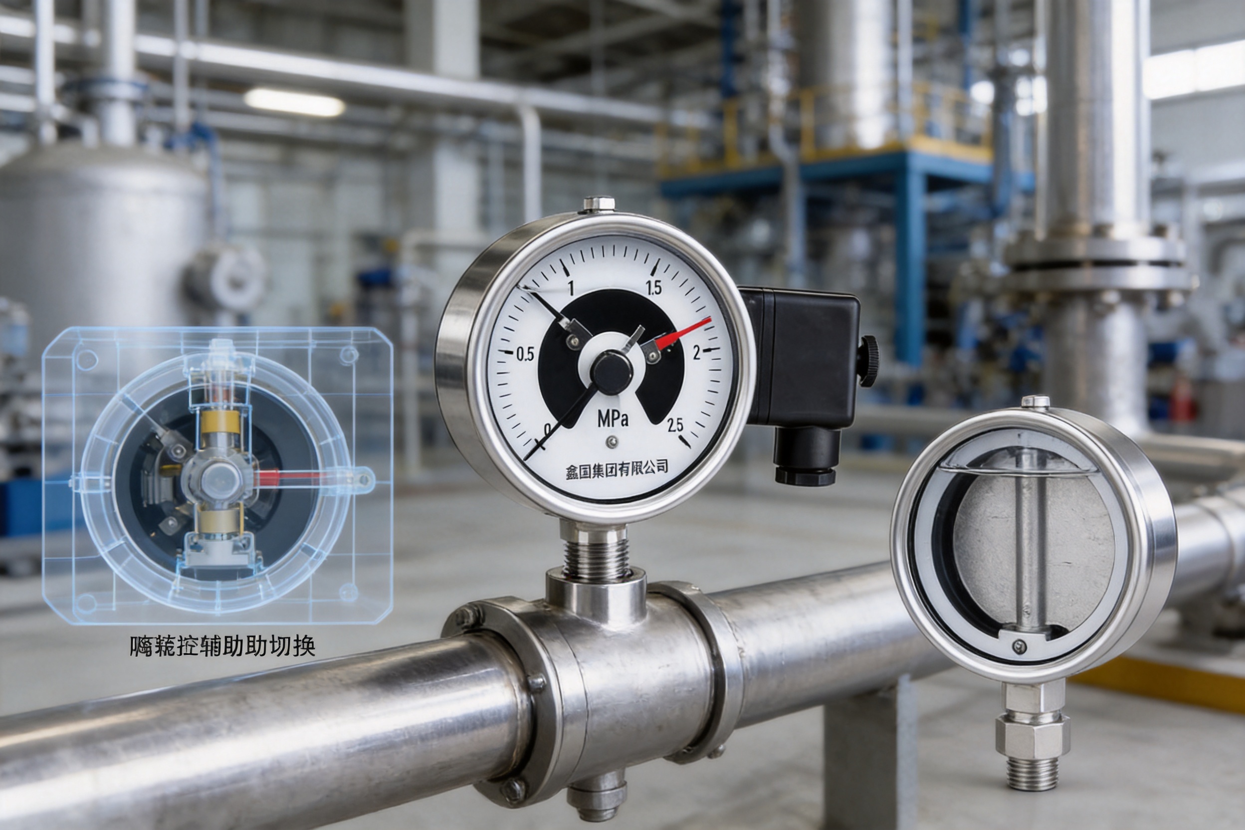
The following table summarizes the principal models and application types provided for the series. The listed ranges represent the available pressure-range families stated in the product information. The final selection should be confirmed against the required unit, scale, connection, medium, and operating conditions.
| Type | Model | Application | Dial Range | Indication Accuracy | Set-Value Accuracy: Make | Set-Value Accuracy: Break | Connection |
| Special Type | XG-YXCA | Ammonia pressure service | 0 to 0.16–60 MPa; −0.1 to 0.06–2.4 MPa series | 2.5 | 2.5 | 4 | M20×1.5 |
| Vibration-Resistant Type | XG-YXC-Z | Magnetic-assisted contact pressure measurement in vibrating service | 0 to 0.6–60 MPa; −0.1 to 0.5–2.4 MPa series | 1.5 | 1.5 | 5 | M20×1.5 |
| Corrosion-Resistant Type | XG-YXC-B-F | Corrosive or humid environments | 0 to 0.6–60 MPa; −0.1 to 0.06–2.4 MPa series | 1.5 | 1.5 | 4 | M20×1.5 |
| Corrosion- and Vibration-Resistant Type | XG-YXC-B-FZ | Corrosive service with mechanical vibration | 0 to 0.6–60 MPa; −0.1 to 0.5–2.4 MPa series | 1.5 | 1.5 | 5 | M20×1.5 |
| Diaphragm Type | XG-YXC/M | Media requiring diaphragm isolation | 0 to 0.16–60 MPa; −0.1 to 0.06–2.4 MPa series | 1.5 | 1.5 | 4 | Various isolators |
| Corrosion-Resistant Diaphragm Type | XG-YXC-B-F/M | Corrosive media with diaphragm isolation | 0 to 0.16–60 MPa; −0.1 to 0.06–2.4 MPa series | 1.5 | 1.5 | 4 | Various isolators |
| Vibration-Resistant Diaphragm Type | XG-YXC-Z/M | Vibration and isolated media service | 0 to 0.6–60 MPa; −0.1 to 0.5–2.4 MPa series | 1.5 | 1.5 | 5 | Various isolators |
| Corrosion- and Vibration-Resistant Diaphragm Type | XG-YXC-FZM | Corrosive, vibrating, and isolated service | 0 to 0.6–60 MPa; −0.1 to 0.5–2.4 MPa series | 1.5 | 1.5 | 5 | Various isolators |
The model designation provides information about the instrument category, control mode, magnetic-assisted contact form, housing, special functions, and diaphragm configuration. The letter A identifies a model suitable for ammonia and ammonia mixtures. B identifies stainless-steel housing construction. F identifies corrosion resistance, Z identifies vibration resistance, and M identifies a diaphragm type.
Pressure range selection has a direct effect on measurement quality, overload protection, and switching stability. The normal operating pressure should generally fall within a central portion of the selected scale rather than remaining close to the maximum value. A range that is too high may reduce the useful resolution of the dial, while a range that is too low may expose the instrument to repeated overload.
Available pressure families include positive-pressure ranges beginning at low values and extending to high-pressure applications, as well as compound or vacuum-pressure ranges. The exact scale should be chosen according to whether the process involves positive pressure, vacuum, or alternating pressure conditions.
The listed indication accuracy for many special configurations is 1.5, while the ammonia special type is listed at 2.5. Set-value accuracy is separately specified for contact making and breaking. This distinction is important because the pointer indication and electrical switching point are different performance characteristics.
Set-value accuracy can be affected by pressure cycling, temperature deviation, vibration, contact adjustment, and the behavior of the process itself. During commissioning, the high and low control points should be checked under conditions representative of actual operation. If a control point is located in a pressure region with constant oscillation, the instrument may switch repeatedly even when its mechanical accuracy is within specification.
The operating environment must be evaluated before selecting the instrument. The product information identifies different temperature and vibration conditions for dedicated, corrosion-resistant, vibration-resistant, and diaphragm configurations.
| Configuration | Medium Temperature | Ambient Temperature | Relative Humidity | Vibration Resistance |
| Dedicated Type | −40 to 70 °C | Not separately stated in the supplied data | Up to 85% | V·H·3 |
| Corrosion-Resistant Type | −40 to 70 °C | Not separately stated in the supplied data | Not separately stated in the supplied data | V·H·3 |
| Vibration-Resistant or Combined Type | −25 to 55 °C | Not separately stated in the supplied data | Up to 90% | V·H·4 |
| Standard Diaphragm Type | Up to 150 °C | −40 to 70 °C | Not separately stated in the supplied data | V·H·3 |
| Corrosion-Resistant Diaphragm Type | −40 to 70 °C | Not separately stated in the supplied data | Not separately stated in the supplied data | V·H·3 |
| Vibration-Resistant or Combined Diaphragm Type | Up to 150 °C | −25 to 55 °C | Not separately stated in the supplied data | V·H·4 |
The supplied technical information uses different environmental descriptions for several models. Before purchase or installation, the exact ambient temperature, medium temperature, humidity, vibration classification, and enclosure requirements should be confirmed for the selected model.
Temperature affects both indication and switching. The specified temperature effect is an indication value of no more than 0.4 percent per 10 °C and a set-point effect of no more than 0.6 °C per 10 °C when the operating temperature deviates from the reference range of 20 ± 5 °C. These values should be considered when the instrument is installed outdoors, near hot equipment, or in a process with significant temperature variation.
Diaphragm isolation is one of the most important features for special process conditions. In a direct-pressure spring-tube gauge, the medium enters the pressure-sensing element. This arrangement may be unsuitable for media containing solid particles, crystallizing components, high viscosity, strong corrosive chemicals, or substances that could block or attack the internal mechanism.
A diaphragm isolator creates a barrier between the process medium and the pressure gauge movement. Process pressure acts on the diaphragm, and the pressure is transferred through a suitable filling system or mechanical structure to the measuring element. The gauge therefore receives the pressure information without allowing the process medium to reach the spring tube core.
Diaphragm selection must consider process temperature, pressure, chemical compatibility, viscosity, solids content, response time, and cleaning requirements. Different isolator structures may be appropriate for different applications. The product family supports various isolators so that the instrument can be adapted to the process rather than forcing the process to match a standard connection.
For strong corrosion or particle-containing media, the diaphragm configuration should be treated as a protective isolation solution, not merely an accessory. Direct contact between an unsuitable medium and the spring tube can cause leakage, loss of accuracy, mechanical failure, or contamination of the process.
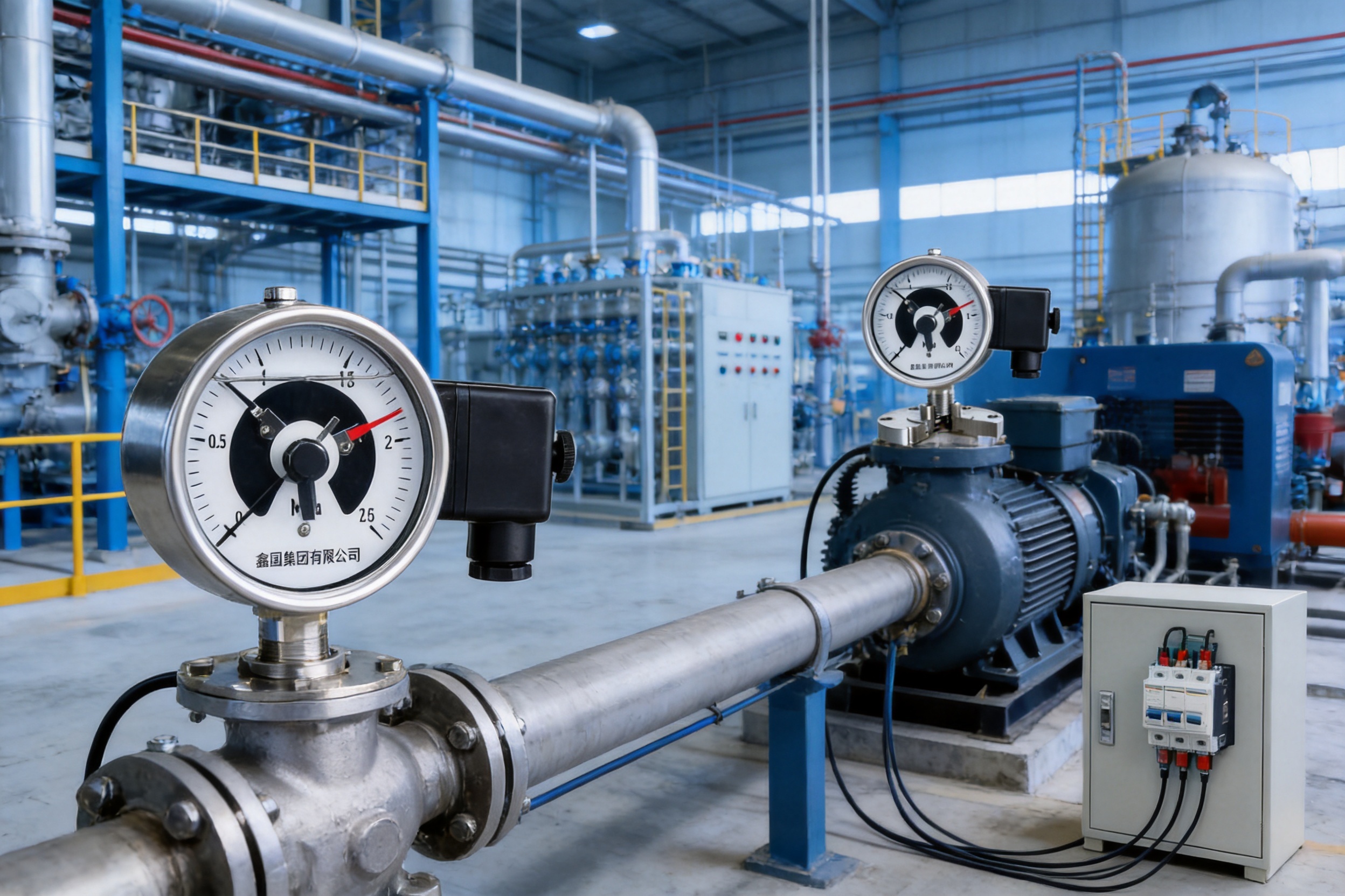
Pumping systems frequently require low-pressure and high-pressure protection. A low-pressure contact can help prevent a pump from running dry or operating below its intended suction condition. A high-pressure contact can stop a pump, activate an alarm, or protect downstream piping.
Outdoor water-treatment systems may expose instruments to moisture, dust, temperature cycling, and vibration. Stainless-steel housing and corrosion-resistant configurations are useful in these environments. Where the liquid contains suspended solids or aggressive chemicals, a diaphragm isolator can improve reliability.
Chemical processes often involve corrosive or reactive media. Local pressure indication remains valuable for operators even when a central control system is present. The electrical contact function can provide a local backup alarm or a direct interlock for equipment protection.
The instrument should be selected with a wetted-material compatibility review. Stainless steel or an alloy suitable for the specific chemical may be required. The diaphragm version is appropriate when direct exposure of the pressure-measuring mechanism is unacceptable.
The ammonia-specific model is intended for ammonia and ammonia mixtures when the complete pressure, temperature, and material conditions are suitable. Ammonia systems require careful material selection, sealing, pressure-range selection, and installation procedures. The instrument should be incorporated into a system designed for the relevant refrigerant and safety requirements.
Local indication enables technicians to observe pressure during inspection and maintenance. The contact function can support high-pressure alarms, low-pressure protection, compressor control, and other external safety circuits.
Compressors create pressure pulsation and mechanical vibration. A vibration-resistant pressure gauge can help maintain more stable indication and switching in these conditions. It can be used to monitor discharge pressure, receiver pressure, lubrication pressure, or auxiliary pressure circuits, provided the selected range and connection are appropriate.
For reciprocating compressors, pressure pulsation may be significant. Additional pulsation dampening, a suitable snubber, or a remote mounting arrangement may be needed. The gauge should not be installed in a location where direct mechanical shock exceeds its design capability.
Hydraulic systems may experience high pressure, rapid pressure changes, vibration, and shock loading. The special gauge can provide visual indication and a pressure-limit signal for pumps, actuators, hydraulic power units, and test equipment. Correct range selection is particularly important because hydraulic pressure spikes can exceed normal operating pressure.
The integrated indication and contact function is suitable for pressure-based interlocks in boilers, vessels, filtration equipment, process skids, utility systems, and production machinery. It can provide a simple mechanical control layer where a fully electronic pressure transmitter is unnecessary or where an independent local switching device is preferred.
The electrical contacts are signal contacts. They should be connected to an external relay, contactor, programmable control input, or other circuit designed for the contact rating. The external switching device should then control the motor, pump, valve, heater, compressor, or other high-power load.
Electrical wiring should be carried out by qualified personnel in accordance with the instrument documentation and applicable electrical regulations. The circuit should include suitable overcurrent protection and should be designed to prevent the gauge contact from carrying a load greater than its rated capacity.
Control logic should be reviewed for both normal and failure conditions. For example, a high-pressure contact may be arranged to de-energize a pump through a normally closed safety circuit, while a low-pressure contact may initiate an alarm through a normally open circuit. The appropriate arrangement depends on the process hazard analysis and the desired fail-safe behavior.
Contact settings should be adjusted only after the process has been isolated or made safe according to the plant’s procedures. Improper adjustment can result in an alarm occurring too late, a pump cycling unnecessarily, or a protective interlock failing to respond at the intended pressure.
The quality of a pressure gauge depends on more than its final appearance. Measurement stability and contact reliability are influenced by material quality, machining, movement assembly, sealing, calibration, electrical inspection, and final testing. Xinguo Group’s manufacturing resources cover industrial instrumentation, alloys, cables, precious metals, and related products, giving the organization a broad technical foundation for instrument production.
The group operates modern production facilities with a reported construction area of approximately 60,000 square meters and employs nearly 300 people, including professional technicians, senior technical experts, engineers, and assistant engineers. This technical workforce supports product development, process improvement, material evaluation, production control, and customer-specific solutions.
Its manufacturing approach is supported by research and development capabilities, advanced equipment, modern production techniques, and inspection procedures at different stages of production. For a special contact pressure gauge, this type of process organization is important because the product combines several functions: pressure measurement, mechanical movement, magnetic switching, environmental protection, and electrical connection.
Material expertise is particularly valuable for special models. Stainless-steel housings, corrosion-resistant wetted components, diaphragm materials, and alloys must be selected according to the service environment. A manufacturer with experience in alloy materials and industrial components can evaluate the relationship between mechanical strength, corrosion resistance, temperature behavior, and manufacturability.
Quality systems also help create repeatability between production batches. Xinguo Group reports certification to ISO 9001 quality-management, ISO 14001 environmental-management, and GB/T 28001 occupational health and safety management systems. These systems provide an organized framework for document control, process management, inspection, corrective action, environmental responsibility, and workplace safety.
The company also states that its products are developed and manufactured with reference to IEC international standards and national and industrial specifications. The applicable standard depends on the particular instrument, electrical contact arrangement, material, and destination market. Customers should request the relevant technical documents and certificates for the exact model ordered.
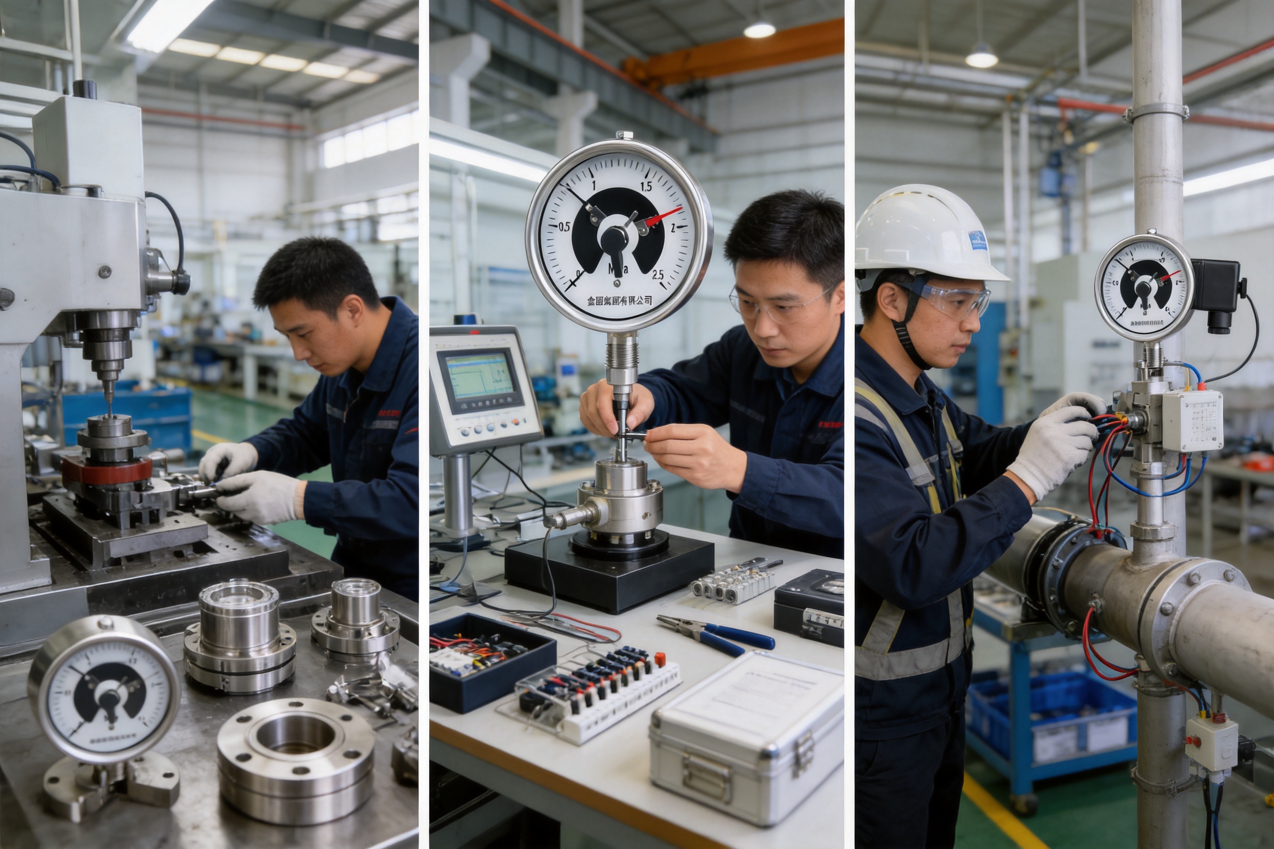
The manufacturing process begins with the selection and preparation of materials for the case, pressure connection, elastic element, movement, contact system, seals, and diaphragm or isolator where required. Materials must be suitable for the specified pressure, temperature, corrosion, and mechanical conditions.
For corrosion-resistant products, the material selection process is central to long-term performance. The material exposed to the process medium may need to differ from the material used for the housing. For diaphragm products, the isolator and its process connection must be selected together with the filling and sealing arrangement.
The pressure-measuring element and mechanical movement must be produced with controlled dimensions and consistent mechanical behavior. The transmission mechanism converts small elastic deformation into pointer movement, so excessive friction, looseness, or inconsistent assembly can affect indication accuracy and switching performance.
The magnetic-assisted contact mechanism also requires controlled assembly. The position of the magnetic components, contact elements, adjustment mechanism, and pointer interface influences the making and breaking points. Consistent production and inspection are therefore necessary for repeatable control settings.
During assembly, the pressure path, movement, dial, pointer, contact device, case, and electrical terminals are integrated. Sealing is important for protecting the internal mechanism from dust and moisture. Diaphragm configurations require additional attention to the isolator, pressure-transfer system, and process connection.
Assembly procedures should prevent contamination of the movement and contact system. The case must also be assembled without distorting the dial, pointer, or contact adjustment mechanism. The result should provide a clear local display and reliable access to the intended electrical terminals.
Calibration verifies the relationship between applied pressure and pointer indication. Contact verification checks the pressure at which the contacts make and break. These are separate tests because a gauge may display pressure correctly while its contact setting requires adjustment.
Testing should cover the selected range and the specified control points. Where the product is intended for vibration, corrosion, or diaphragm service, the corresponding configuration should be checked for correct assembly and integrity. Records of inspection and calibration support traceability and maintenance planning.
Final inspection may include visual examination, dial and pointer checks, pressure-leak checks, electrical continuity checks, contact operation checks, connection verification, and review of product identification. A complete inspection process helps ensure that the supplied instrument matches the order requirements.
The gauge should be installed where it can be read easily and where the pressure connection is protected from unnecessary vibration and mechanical stress. The process connection should be properly supported, and the instrument should not be used to support the weight of adjacent piping.
Before installation, confirm that the pressure range, thread size, medium compatibility, temperature rating, housing material, diaphragm arrangement, and contact requirements match the application. The M20×1.5 connection is listed for several standard models, while diaphragm models use various isolator connections.
Where pressure pulsation is present, a suitable pulsation dampener, snubber, capillary, or remote diaphragm arrangement may be considered. The selected solution must not introduce an unacceptable response delay for the control function. For severe vibration, the gauge may need a vibration-resistant version and a mechanically stable mounting bracket.
The instrument should be protected from direct impact, excessive heat, corrosive vapors, and water accumulation. Outdoor installations may require additional shielding or an enclosure arrangement appropriate for the local environment. Cable entries and electrical connections should be sealed and routed to prevent water from entering the case.
After installation, the pressure system should be checked for leakage. The pointer should return to the expected zero position when the pressure connection is isolated and depressurized. The alarm and interlock circuits should be tested at safe commissioning conditions before the equipment is placed into normal service.
Regular inspection should include the dial, pointer, case, pressure connection, electrical terminals, contact function, and zero position. The inspection interval should be based on process criticality, pressure cycling, vibration, corrosion, and the manufacturer’s maintenance recommendations.
If contact misoperation occurs, first evaluate process pulsation and mechanical vibration. A vibration-resistant or shock-resistant configuration may be required. Next, inspect for contact oxidation, contamination, loose wiring, incorrect adjustment, or excessive electrical load.
Control points should not be positioned within a pressure range that fluctuates continuously during normal operation. If the process must operate near a switching point, the external control logic may require a time delay, hysteresis, latching circuit, or separate controller to prevent repeated cycling.
Long-term overpressure should be avoided. Even when the movement has improved overload resistance, repeated operation beyond the rated range can permanently deform the sensing element or change the calibration. Pressure relief devices and suitable isolation valves should be used in systems where abnormal pressure is possible.
For diaphragm instruments, inspect the diaphragm and process connection for blockage, corrosion, crystallization, or deposits. Do not disassemble a filled diaphragm system without appropriate technical procedures. A damaged or leaking isolator can affect measurement accuracy and may expose personnel to hazardous process media.
The following questions can help determine the correct configuration:
What is the normal operating pressure, maximum pressure, and possible pressure surge? Select a range that provides adequate resolution while allowing sufficient overload margin.
Is the medium clean and non-corrosive, or does it contain particles, crystals, high viscosity, or aggressive chemicals? If direct contact with the spring tube is unsuitable, select a diaphragm configuration.
Is the equipment exposed to vibration, pulsation, mechanical shock, or rapid cycling? If so, consider the vibration-resistant version and review the installation arrangement.
Does the environment contain humidity, dust, corrosive vapor, or outdoor exposure? Select a suitable housing and corrosion-resistant configuration, and protect the electrical connections.
Are ammonia or ammonia mixtures present? Use the dedicated ammonia configuration only after confirming material compatibility and the complete operating conditions.
What control action is required? Define whether the contact will provide a high-pressure alarm, low-pressure alarm, pump start, pump stop, compressor protection, or another interlock.
Will an external relay or contactor be used? The gauge contacts should not directly drive high-power equipment. Confirm contact ratings and provide the required external control components.
What are the ambient and medium temperatures? Consider the specified temperature effect on both indication and set point, especially where the operating temperature differs substantially from 20 ± 5 °C.
The special version uses an enhanced magnetic-assisted contact structure and can be configured with stainless-steel materials, corrosion-resistant construction, vibration resistance, and diaphragm isolation. It is intended for corrosive media, pressure pulsation, mechanical vibration, viscous fluids, and other harsh conditions that may exceed the normal application range of a conventional contact gauge.
No. The contacts are signal outputs with limited current capacity. A suitable external relay, contactor, control module, or relay-controlled pump and valve circuit must be used. Direct connection to a high-power load may burn or weld the contacts.
It can be used when the correct diaphragm or isolator configuration and compatible materials are selected. The process medium should not directly contact the spring tube or other components that are unsuitable for the medium. Material compatibility must be reviewed for the exact chemical, temperature, concentration, and pressure.
Check for excessive pressure pulsation, mechanical vibration, contact oxidation, loose wiring, incorrect contact adjustment, and an unsuitable switching point. A vibration-resistant model may be required. Avoid setting a control point within a pressure band that fluctuates continuously.
No. A diaphragm model is better when the process medium requires isolation, but it may add complexity and can influence response characteristics. A standard direct-pressure model may be preferable for clean, compatible media. The configuration should be selected according to the process rather than assumed to be universally superior.
Depending on the control function, the gauge may be connected to relays, contactors, programmable control inputs, pump starters, valve control circuits, alarms, or interlock systems. The external device must be compatible with the contact rating and the required fail-safe logic.
According to the supplied data, the indication temperature effect is no more than 0.4 percent per 10 °C, and the set-point temperature effect is no more than 0.6 °C per 10 °C when the operating temperature differs from 20 ± 5 °C. The exact operating limits depend on the selected configuration.
Corrosion-resistant and stainless-steel configurations can be suitable for humid outdoor environments when the temperature, humidity, vibration, and enclosure conditions remain within the specified limits. The electrical connections should be protected against water ingress, and the gauge should be shielded from direct impact and severe weather where necessary.
Provide the required pressure range, pressure unit, medium name and composition, operating and maximum pressure, medium and ambient temperature, vibration conditions, connection size, housing material, diaphragm requirement, contact function, contact rating, and quantity. This information allows the correct model to be selected.
The XG/YXC series special magnetic-assisted electric contact pressure gauge is designed for industrial applications in which a basic pressure gauge is not sufficient and a fully electronic measurement system is not necessary. It combines local pressure indication with magnetic-assisted electrical contact control and adds configuration options for corrosion, vibration, ammonia service, pressure pulsation, viscous media, and difficult process fluids.
Its main advantages are the strengthened magnetic-assisted contact system, improved resistance to contact misoperation, stainless-steel and corrosion-resistant options, vibration-resistant designs, diaphragm isolation, integrated measurement and interlock control, and strengthened mechanical construction. These features make it suitable for pumps, compressors, chemical equipment, ammonia systems, hydraulic machinery, water-treatment installations, pressure vessels, and general process-control equipment.
The product’s performance depends on correct selection and installation. Pressure range, material compatibility, diaphragm type, environmental conditions, electrical loading, and control logic must all be evaluated before ordering. With appropriate engineering and maintenance, the instrument can provide a practical and economical pressure-monitoring and alarm solution for demanding industrial service.
Xinguo Group’s capabilities in industrial instrumentation, alloy materials, cables, research and development, production, inspection, and quality management provide a strong manufacturing foundation for this product family. Its reported ISO quality, environmental, and occupational health and safety systems further support a structured approach to reliable industrial manufacturing.
1. Xinguo Group Co., Ltd., Product Technical Information for the XG/YXC Series Special Magnetic-Assisted Electric Contact Pressure Gauge.
2. Xinguo Group Co., Ltd., Product Data for Magnetic-Assisted Electric Contact Pressure Gauges and Related Pressure Instruments.
3. International Electrotechnical Commission, General Principles for Electrical Equipment and Industrial Measurement Applications.
4. ISO 9001, Quality Management Systems—Requirements.
5. ISO 14001, Environmental Management Systems—Requirements with Guidance for Use.
6. GB/T 28001, Occupational Health and Safety Management System Requirements.
7. General industrial guidance on bourdon-tube pressure gauges, diaphragm seals, pressure switches, and mechanical contact protection.
8. General engineering practice for pressure-instrument selection, process-medium compatibility, vibration control, electrical interlocking, and pressure-system maintenance.



 INQUIRY
 English
 عربى
 русский
 中文简体