
Accurate pressure measurement is essential to the safe, efficient, and stable operation of modern industrial systems. Refineries, chemical plants, power stations, water-treatment facilities, metallurgical production lines, vacuum systems, and oil and gas pipelines all depend on reliable instruments to monitor process conditions. A pressure transmitter must do more than detect pressure. It must convert process pressure into a stable control signal, withstand temperature changes and vibration, communicate with automation systems, remain accurate over long operating periods, and provide dependable service in challenging field environments.
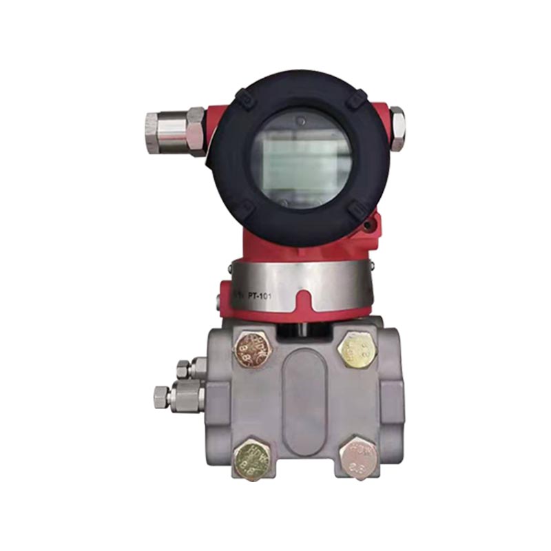
The XG3051T differential pressure/absolute pressure transmitter is designed as a direct-connected intelligent pressure measurement instrument for these requirements. It is available in gauge-pressure and absolute-pressure configurations and uses a capacitive sensing structure with a 316L stainless-steel diaphragm as the standard process-wetted material. Its primary output is a two-wire 4–20 mA signal, with HART digital communication available for configuration, diagnosis, calibration, and process-data access.
Unlike many conventional pressure measurement arrangements that require separate impulse piping, manifolds, remote seals, or additional pressure accessories, the XG3051T can be installed directly on a process pipeline or vessel through its process connection. This structure can simplify installation, reduce the number of potential leakage points, and improve response in applications where short transmission paths are beneficial.
The transmitter combines a broad pressure range, adjustable range settings, optional local display, local or manual calibration, explosion-proof treatment options, multiple process connections, selectable diaphragm and filling-fluid materials, and industrial communication compatibility. These features make it suitable for both general pressure monitoring and more specialized applications such as vacuum measurement, distillation, negative-pressure service, and oxygen-related measurement when the appropriate material and oil-free options are selected.
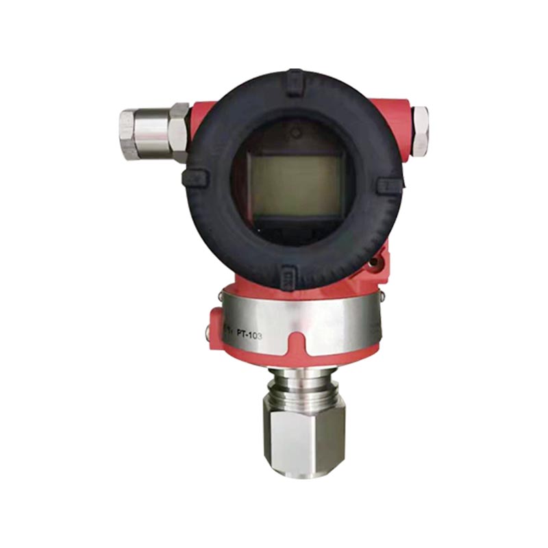
XG3051T Differential pressure/absolute pressure transmitter
The XG3051T is a direct-connected intelligent transmitter intended to measure the pressure of gases, liquids, and vapors. Depending on the selected sensing configuration, it measures either gauge pressure or absolute pressure. The measured pressure acts on the sensing diaphragm, causing a small mechanical displacement. The capacitive sensing system converts this displacement into an electrical signal, which is processed by the transmitter electronics and converted into a standard industrial output.
For a gauge-pressure model, the measured value is referenced to local atmospheric pressure. If atmospheric pressure changes, the reference condition changes with it. Gauge-pressure transmitters are therefore commonly used for ordinary pipeline pressure, tank pressure, pump discharge pressure, utility systems, and general process monitoring.
An absolute-pressure model uses an absolute vacuum reference. It is not affected by changes in local atmospheric pressure in the same manner as a gauge-pressure model. Absolute pressure is particularly useful for vacuum systems, distillation equipment, evaporation processes, vacuum drying, low-pressure process control, and applications in which pressure must be compared with a fixed vacuum reference.
The two versions are not interchangeable simply through software configuration. Their sensing structures and reference conditions are different. Selecting the correct pressure type during ordering is therefore essential. A system designer should determine whether the process variable is referenced to atmospheric pressure or to absolute vacuum before choosing the model and range code.
The standard sensing diaphragm is made from 316L stainless steel. This material provides a useful combination of corrosion resistance, mechanical strength, cleanliness, and compatibility with many industrial gases and liquids. For more aggressive media, Hastelloy C diaphragm options are available. The correct material should be selected after considering the process composition, concentration, temperature, pressure, cleaning procedure, and any possible contaminants.
The diaphragm is the primary barrier between the process medium and the internal sensing system. In a direct-connected design, the process medium contacts the diaphragm directly through the process connection. This eliminates the need for long impulse lines in many installations and reduces the influence of line plugging, condensation, freezing, and trapped gas or liquid. However, direct connection also makes material selection and process-temperature evaluation especially important.
The XG3051T uses a two-wire 4–20 mA DC signal for connection to distributed control systems, programmable logic controllers, safety monitoring equipment, data acquisition units, and other industrial control devices. The 4–20 mA standard remains widely used because it provides good noise immunity, long-distance transmission capability, and a live-zero signal. A reading below the normal operating range can help identify wiring or instrument faults because zero process pressure normally corresponds to approximately 4 mA rather than 0 mA.
HART communication is available for digital access to configuration parameters and diagnostic information. Through a HART controller or compatible host system, users can review the measurement range, adjust zero and span, configure damping, inspect alarm settings, and perform calibration procedures. An optional LCD or OLED display can show the local pressure value and support on-site verification without requiring a separate portable display instrument.
A major advantage of the XG3051T is its direct-connected structure. Traditional pressure measurement systems may require impulse tubing, three-valve or five-valve manifolds, condensate pots, heat tracing, remote seals, brackets, and multiple threaded connections. Each additional component increases installation time, material cost, maintenance requirements, and the number of possible leak paths.
By installing directly on a process pipeline or vessel, the XG3051T can provide a more compact measurement arrangement. The shorter pressure path can reduce the risk of pressure lag caused by blocked or restricted impulse lines. It can also simplify commissioning in locations where access is limited or where the process layout makes conventional impulse piping difficult.
Direct connection does not eliminate the need for engineering review. The process connection, pressure rating, temperature, vibration, accessibility, and chemical compatibility must still be checked. In applications involving very high temperature, crystallizing media, highly viscous fluids, severe pulsation, or strong corrosion, a remote seal, cooling arrangement, snubber, or special diaphragm may be more appropriate.
Many industrial facilities require both gauge and absolute pressure measurements. Using a product family that covers both measurement principles can simplify procurement, training, spare-parts planning, and maintenance. The XG3051T product range allows users to select the appropriate sensing reference without changing the general installation and communication philosophy.
Gauge-pressure versions cover low-pressure monitoring through high-pressure service. Absolute-pressure versions cover lower and medium absolute-pressure ranges suited to vacuum and low-pressure applications. This allows the same engineering team to apply consistent commissioning and diagnostic methods across different process areas.
The transmitter supports multiple range codes and adjustable ranges. The selected range can be adjusted within the upper and lower limits of the applicable range code, provided that the calibrated span is no less than the minimum span. Selecting a range code with the lowest practical turndown ratio is recommended because it generally improves measurement performance and reduces the effect of operating far below the nominal sensor capability.
Gauge-pressure range codes include B, C, D, F, G, H, I, and J. These cover pressures from the low-kilopascal level to as high as 60 MPa, depending on the selected code. Absolute-pressure range codes include L, M, and O, covering absolute ranges from low-pressure vacuum-related service to approximately 3 MPa absolute.
Compatibility with 4–20 mA and HART communication gives the XG3051T a practical advantage over basic analog-only transmitters. A purely analog transmitter may require manual adjustment at the instrument or the use of additional calibration equipment. With HART communication, technicians can access configuration data without removing the instrument from service, subject to the requirements of the plant control system and maintenance procedures.
The communication load range is specified as 230–600 ohms, and the power supply is normally 24 VDC. The allowable loop load depends on the supply voltage and maximum current. System designers should verify cable resistance, barrier resistance, input resistance, and any safety equipment installed in the loop before commissioning.
The product can be supplied without a display, with an LCD display with backlight, or with an OLED display. A local display is useful during commissioning, field inspection, zero adjustment, and troubleshooting. It allows technicians to compare the transmitter’s indicated pressure with an external reference or process condition.
Display selection must be considered alongside ambient temperature. The supplied specifications identify different temperature limits for configurations with LCD or specific sealing materials. The OLED option supports a lower temperature range than the LCD option in the listed configuration. Users should therefore select the display according to the expected environmental temperature rather than treating the display as a purely visual accessory.
The transmitter housing is designed for industrial field installation. Standard specifications identify an IP67 enclosure protection rating, while product introductions may describe IP65 protection for certain configurations or general product literature. The exact protection rating should be confirmed against the final configuration, sealing materials, cable entry, and installation method.
Explosion-proof options include an intrinsic-safety version and a flameproof version under the listed certification options. Additional cable-entry devices can be selected where required. Hazardous-area installation must comply with the applicable local regulations, certification requirements, wiring rules, grounding practices, and barrier limitations. The transmitter’s certification does not replace the requirement for a properly engineered intrinsically safe or flameproof system.
The gauge-pressure configuration provides several range codes for different pressure levels. The B code is intended for low-pressure measurement, with a range capability of approximately 0.6 to 6 kPa and a listed span extending from approximately −6 to +6 kPa. This range is suitable for low-pressure air, ventilation, filter monitoring, and some tank or duct applications.
The C code covers approximately 2 to 40 kPa, while the D code covers approximately 2.5 to 250 kPa. The F code extends from approximately 30 kPa to 3 MPa. These ranges can support pump discharge monitoring, hydraulic systems, process skids, water-treatment equipment, and medium-pressure gas or liquid service.
The G, H, I, and J codes cover higher pressure levels. Depending on the selected code, the upper measurement limit ranges from approximately 10 MPa to 60 MPa. These higher ranges may be applied to high-pressure process pipelines, hydraulic equipment, oil and gas systems, pressure testing, and specialized industrial machinery.
The absolute-pressure L code covers approximately 2 to 40 kPa absolute, with an adjustable span from 0 to 40 kPa absolute. This type is appropriate for low absolute-pressure service and some vacuum applications. The M code extends to approximately 250 kPa absolute, and the O code extends to approximately 3,000 kPa absolute.
Absolute pressure should be selected when atmospheric pressure fluctuations would introduce an unacceptable error into the process measurement. This is common in vacuum distillation, evaporation, vacuum drying, laboratory process systems, and applications in which boiling or vapor pressure relationships are controlled against absolute pressure.
| Configuration | Range Code | Approximate Measurement Capability | Typical Application Direction |
| Gauge pressure | B | 0.6–6 kPa | Low-pressure air, ducts, filters, ventilation |
| Gauge pressure | C | 2–40 kPa | Low-pressure liquids and gases |
| Gauge pressure | D | 2.5–250 kPa | Tanks, pumps, water treatment, process skids |
| Gauge pressure | F | 30 kPa–3 MPa | Medium-pressure pipelines and hydraulic systems |
| Gauge pressure | G | 0.1–10 MPa | High-pressure industrial service |
| Gauge pressure | H | 0.21–21 MPa | High-pressure process systems |
| Gauge pressure | I | 0.4–40 MPa | High-pressure machinery and pipelines |
| Gauge pressure | J | 0.6–60 MPa | Very high-pressure applications |
| Absolute pressure | L | 2–40 kPa absolute | Vacuum and low absolute-pressure service |
| Absolute pressure | M | 2.5–250 kPa absolute | Vacuum, evaporation, and low-pressure processes |
| Absolute pressure | O | 30–3,000 kPa absolute | Medium absolute-pressure applications |
The values in the table are summarized from the product range information. Final selection should use the ordering code, calibration certificate, process conditions, and project specification. The stated range capability is not the same as the normal operating range. For best accuracy and stability, the normal process pressure should generally fall within a practical portion of the selected range rather than near the extreme limits.
The reference accuracy for the listed standard adjustment range is approximately ±0.075%, including zero-based linearity, hysteresis, and repeatability. Depending on the ordering code, product configurations may offer different basic accuracy levels, including options described as ±0.04%, ±0.05%, ±0.075%, or other specified values. Users should confirm the accuracy associated with the exact ordered code rather than relying only on the general product description.
When the turndown ratio exceeds 10, an additional effect is identified as ±(0.0075 × TD) percent, where TD is the maximum range divided by the adjusted range. This is an important consideration when selecting a broad range sensor and programming a very narrow operating span. A properly selected range code can reduce turndown and improve the practical performance of the installed instrument.
Industrial pressure transmitters are exposed to changing ambient temperatures, and temperature variation can affect zero point, span, electronics, sealing materials, and display operation. The listed ambient temperature range is generally −40 to 85 °C, with a more limited range for some LCD and sealing-ring configurations.
For the −20 to 65 °C temperature interval, the total ambient-temperature effect for B/L range codes is listed as ±(0.30 × TD + 0.20)% of span. For other ranges, the corresponding value is listed as ±(0.20 × TD + 0.10)% of span. Similar values are provided for the extended intervals from −40 to −20 °C and from 65 to 85 °C. These figures should be included in the measurement uncertainty analysis when the transmitter is installed outdoors or near hot equipment.
Good installation practice can reduce temperature-related error. The transmitter should not be mounted directly beside hot surfaces, steam outlets, or strong radiant heat sources unless suitable thermal protection is provided. Where the process connection itself becomes hot, the process temperature at the diaphragm and the ambient temperature at the electronics should be evaluated separately.
Long-term drift is listed as approximately ±0.2% of span per year for B/L range codes and ±0.1% of span per year for other range codes. These values provide a basis for planning periodic verification and recalibration. The actual maintenance interval should be determined by process criticality, regulatory requirements, historical performance, environmental severity, and the consequences of an incorrect pressure signal.
Stable construction, controlled manufacturing processes, appropriate material selection, and correct installation all contribute to long-term performance. A transmitter that is mechanically overloaded, exposed to excessive vibration, subjected to unsuitable chemicals, or installed with a damaged seal may drift or fail more quickly than the nominal specification suggests.
The listed over-range effect is approximately ±0.075% of span. Separate overload limits are provided for different range groups. For example, the 6 kPa range group has an overload limit of approximately 0.2 MPa, the 40 kPa group approximately 1 MPa, the 250 kPa group approximately 4 MPa, and the 3 MPa group approximately 16 MPa. Higher pressure groups have corresponding overload values up to approximately 70 MPa for the highest listed range.
Overload capability should not be interpreted as permission to operate continuously at the overload limit. Pressure surges, water hammer, compressor pulsation, valve closure, and accidental isolation can exceed normal process pressure. Where these events are possible, the system should include appropriate protection such as pulsation dampers, snubbers, relief devices, controlled valve operation, or a pressure-rated manifold.
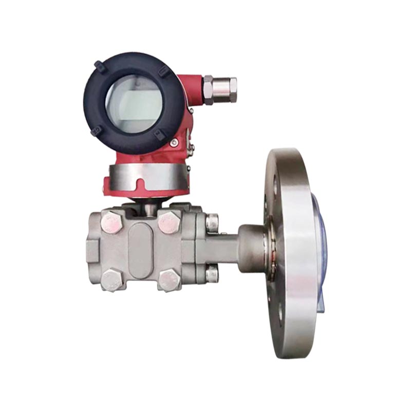
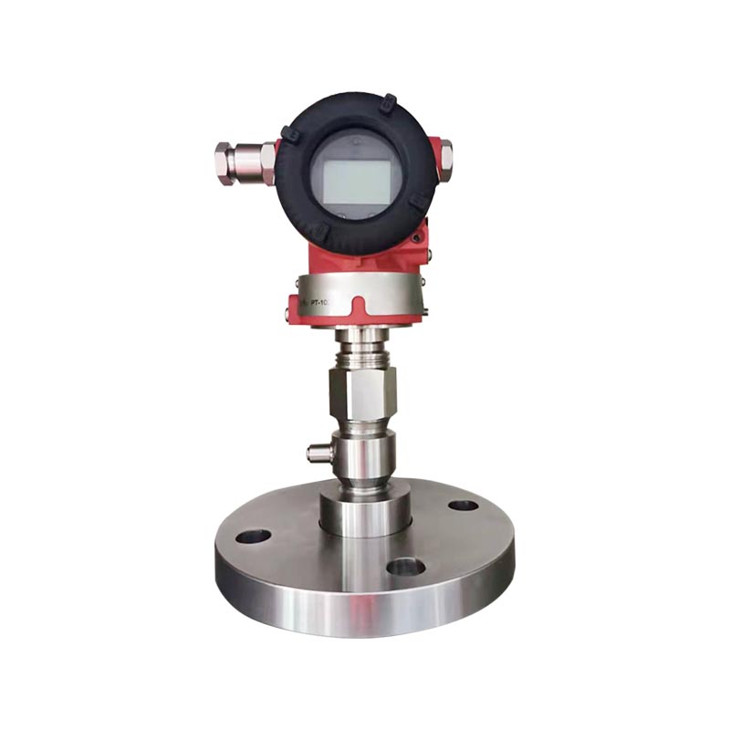
The standard process connection is a 1/2-inch NPT internal thread. Adapters and alternative connection forms are available, including 1/2-inch NPT external thread, G1/2 external thread, M20 × 1.5 external thread, 1/4-inch NPT external thread, and a DIN 28403 KF16 or ISO 2861 vacuum connection.
The KF16 vacuum connection is intended for the applicable low-pressure range and is limited to service within the stated pressure restrictions. Vacuum applications require particular attention to gasket material, cleanliness, leak testing, outgassing, and installation orientation. The process connection must be compatible with the vacuum system’s flange standard and expected operating pressure.
The standard wetted diaphragm and process connection are 316L stainless steel. Hastelloy C diaphragm options are available for more demanding corrosion conditions. The filling fluid may be silicone oil or fluorinated oil. Fluorinated filling fluid is relevant for certain oxygen measurement applications and other services where silicone oil is unsuitable. The oil-free treatment option includes fluorinated oil filling, an FKM seal ring, and specified pressure and temperature limitations.
Material selection must consider the complete process, not only the main fluid name. Trace contaminants, moisture, chlorides, acids, alkaline compounds, cleaning agents, and high-temperature reaction products can change compatibility. When the medium is strongly corrosive or chemically uncertain, operating conditions should be submitted for technical confirmation before ordering.
The transmitter uses an M20 × 1.5 cable gland arrangement, with terminals suitable for conductors from approximately 0.5 to 2.5 mm². The electrical wiring should be installed in accordance with the loop diagram and the requirements of the selected hazardous-area certification, if applicable.
The typical supply voltage is 24 VDC, with a usable supply range identified as approximately 12–42 VDC depending on the loop load. The maximum supply voltage is 42 VDC. The available load must satisfy the relationship between supply voltage, minimum transmitter voltage, and maximum loop current. When a HART communicator is used, the loop must also provide the required communication resistance, normally within the specified 230–600 ohm range.
Cables should be routed away from high-current power conductors, variable-frequency drive output cables, large motors, and sources of electromagnetic interference. Shielding and grounding should follow the plant instrumentation standard. The shield arrangement should be designed to avoid ground loops while maintaining effective protection against interference.
Before energizing the transmitter, technicians should verify polarity, terminal tightness, cable insulation, power-supply voltage, loop resistance, and barrier compatibility. Incorrect polarity or inadequate supply voltage may result in an apparently failed transmitter even when the instrument itself is functioning correctly.
The manufacturer behind the XG3051T is Xinguo Group Co., Ltd., an industrial enterprise established in 1997 in Anhui Province, China. The group includes specialized companies involved in instrumentation, alloy materials, cables, and precious metals. This broader manufacturing structure provides access to capabilities that support the development and production of industrial measurement products and related materials.
The group operates a substantial production and engineering base with a reported construction area of approximately 60,000 square meters and a workforce of nearly 300 people, including professional technicians, senior technical experts, senior engineers, engineers, and assistant engineers. This combination of production capacity and technical personnel supports product development, process improvement, quality inspection, and customer-specific technical assistance.
Pressure transmitter performance depends strongly on the quality and consistency of the diaphragm, process connection, filling fluid, seals, housing, electronics, and cable-entry components. The product’s defined material options allow manufacturing and engineering teams to match the transmitter to different process conditions.
316L stainless steel is used for standard diaphragm and process-connection construction. Hastelloy C is available where additional corrosion resistance is required. Silicone oil and fluorinated oil options provide different compatibility characteristics. Nitrile rubber is listed for the standard housing seal, while FKM is available for specified oxygen-related or special-service configurations.
Material traceability and controlled incoming inspection are important in this type of product. Verification may include dimensional checks, material identification, sealing inspection, electrical testing, pressure testing, sensor signal evaluation, and calibration against reference equipment. Consistent material control helps reduce batch-to-batch variation and supports reliable field service.
The manufacturer reports modern production techniques and strict inspection procedures at each stage of manufacturing. For an intelligent pressure transmitter, these stages typically include mechanical component preparation, diaphragm and sensing assembly, filling and sealing, electronics assembly, enclosure integration, wiring inspection, software or communication verification, pressure calibration, temperature evaluation, and final functional testing.
Calibration is particularly important because pressure transmitters convert a physical quantity into a standardized electrical signal. Reference pressure sources must be suitable for the applicable range and accuracy. The transmitter may be checked at multiple pressure points to verify zero, span, linearity, hysteresis, repeatability, and alarm behavior. Communication functions can also be checked through the digital interface.
Environmental and electromagnetic compatibility testing further strengthens the product’s industrial suitability. The listed EMC schedule includes radiated and conducted emission tests, electrostatic discharge immunity, radio-frequency electromagnetic-field immunity, power-frequency magnetic-field immunity, electrical fast-transient immunity, surge immunity, and conducted radio-frequency disturbance immunity. Such testing helps evaluate how the transmitter behaves in electrically demanding plant environments.
Xinguo Group reports certification to ISO 9001 quality management, ISO 14001 environmental management, and GB/T 28001 occupational health and safety management systems. These systems provide a framework for documented processes, continual improvement, environmental responsibility, employee safety, corrective action, and controlled customer service.
The company also states that its products comply with IEC international standards as well as applicable national and industrial specifications. Compliance claims should always be matched with the specific model, certificate, ordering code, and destination-market requirements. Nevertheless, a documented quality system and an established export-oriented manufacturing structure can provide confidence for international users seeking consistent supply and technical support.
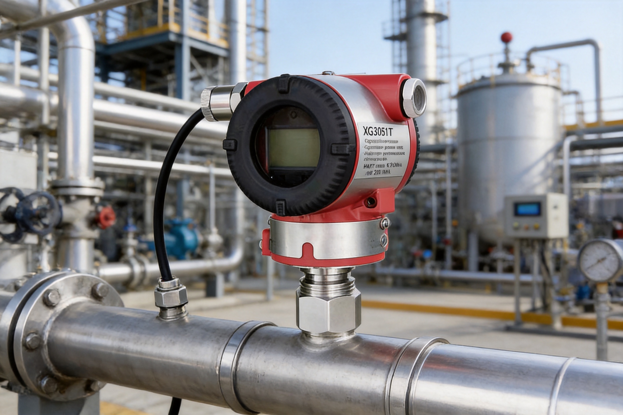
Pressure measurement is used throughout reactors, storage tanks, separators, process pipelines, pumps, compressors, and utility systems. The XG3051T can be used for ordinary gauge-pressure monitoring or absolute-pressure measurement where vacuum and distillation conditions are involved.
In chemical service, diaphragm and seal compatibility should be reviewed carefully. A Hastelloy C diaphragm, fluorinated filling fluid, or special seal may be required. Direct connection can reduce the length of process tubing and may help limit the accumulation of liquid or solid deposits in an impulse line, but the process temperature and chemical exposure at the transmitter must still remain within acceptable limits.
Power plants and utility facilities use pressure transmitters in water systems, feedwater equipment, cooling circuits, fuel systems, compressed air networks, steam-related auxiliary systems, and environmental-control equipment. The product’s 4–20 mA output and HART communication allow integration with plant control systems and maintenance tools.
Outdoor power facilities may experience wide temperature changes, rain, dust, vibration, and electromagnetic interference. Proper enclosure sealing, cable-entry selection, grounding, and mounting are essential. Where the transmitter is installed near hot equipment, thermal exposure should be evaluated against the ambient and process-temperature specifications.
Water-treatment systems require pressure monitoring in raw-water lines, filtration equipment, dosing systems, pumps, pressure vessels, membrane systems, and distribution networks. Low and medium gauge-pressure range codes may be suitable for many of these duties.
For corrosive dosing chemicals or contaminated water, the wetted materials should be checked against the actual chemical composition. The direct-connected design can support compact skids and packaged equipment where limited space makes conventional impulse piping inconvenient.
Pipeline networks require reliable pressure information for pump control, leak detection, pressure balancing, process monitoring, and equipment protection. Higher-range gauge-pressure models can be selected for high-pressure applications, while absolute-pressure versions may be used in specialized vacuum or process-conditioning systems.
Oil and gas installations may be located in hazardous areas, making certification, cable-entry selection, grounding, and system documentation important. The intrinsic-safety and flameproof options provide alternatives for different plant-area classifications, but the complete installation must be evaluated by qualified personnel.
Metallurgical plants often combine high temperature, vibration, dust, hydraulic pressure, cooling-water systems, gas lines, and heavy machinery. Pressure instruments may be installed on hydraulic units, furnace-related auxiliary systems, gas distribution lines, dust-removal equipment, and cooling circuits.
In these environments, the transmitter should be protected from excessive radiant heat, strong vibration, mechanical impact, and dust ingress. A suitable bracket, protective shield, impulse snubber, or remote mounting arrangement may be required depending on the application.
The transmitter should be installed on a pressure connection that is clean, correctly threaded, and rated for the process pressure. Thread sealant must be compatible with the process and should not be allowed to enter the sensing port. Excessive tightening torque can damage the process connection or sensing structure.
The mounting position should allow access to the electrical terminals, display, and adjustment controls. The instrument should be supported adequately when installed on a vibrating pipeline. A mounting bracket can be selected in stainless steel or galvanized carbon steel when the process arrangement requires additional mechanical support.
Changes in mounting position parallel to the diaphragm surface are not expected to cause significant zero drift. When the mounting-position deviation exceeds 90 degrees relative to the diaphragm surface, the listed zero drift is less than 0.25 kPa for range C and less than 0.15 kPa for other ranges. Any remaining zero shift can be corrected by zero adjustment, provided the correction is within the permitted calibration range.
The transmitter should not be exposed to a medium temperature or ambient temperature beyond the specified range. If the process is hotter than the transmitter electronics can tolerate, an appropriate cooling arrangement, stand-off connection, impulse line, or remote seal may be necessary.
In cold environments, freezing of water or condensation in the process connection can affect measurement. The installation should prevent liquid accumulation where freezing is possible. For steam or condensing vapor applications, the pressure connection and installation orientation should be designed to maintain a stable condensate seal and prevent excessive heat transfer to the transmitter.
Commissioning should begin with a documentation review. Verify the model code, pressure type, range, diaphragm material, process connection, output type, display, hazardous-area treatment, and accessories against the purchase specification.
After mechanical and electrical installation, confirm that the process isolation valves are in the correct position and that the transmitter is not exposed to an unexpected pressure surge. Check the loop current at zero or known pressure, compare the local display if fitted, and use HART communication to verify the programmed range, units, damping, alarm mode, and output configuration.
The transmitter can be calibrated manually or through a HART controller. Calibration should use a suitable reference pressure source and should be performed only after the process has been isolated safely. Any zero adjustment should be made when the transmitter is at the correct reference condition for the selected gauge or absolute-pressure model.
Routine maintenance should include visual inspection of the housing, cable gland, process connection, mounting bracket, wiring, grounding, and display. Inspect for corrosion, mechanical damage, moisture ingress, loose terminals, blocked process ports, and signs of leakage.
Periodic verification should compare the transmitter output with a calibrated reference. The interval can be based on the stated long-term stability, process criticality, operating history, and quality requirements. Instruments used in custody-related, safety-related, or highly regulated applications may require more frequent verification than instruments used only for general indication.
If the output is absent or fixed at an unexpected value, first verify the 24 VDC supply and measure the voltage at the transmitter terminals under load. A supply may appear normal without load but fall below the required level when connected to the loop.
Next, inspect polarity, terminal tightness, cable continuity, barrier connections, fuses, isolators, and the control-system input. If the loop is intact, check whether the transmitter is in an alarm state. The configurable alarm limits include a low alarm of approximately 3.7 mA, a high alarm of approximately 21 mA, and a hold mode that maintains the valid current value before a fault. The factory default is identified as high alarm.
Numerical jumps may be caused by unstable process pressure, pump pulsation, valve movement, air bubbles, liquid slugs, blockage, vibration, electromagnetic interference, loose wiring, or insufficient damping. Inspect the process connection and compare the transmitter reading with a mechanical gauge or calibrated test instrument where safe.
The amplifier damping constant is listed as 0.1 seconds, while the sensor time constant may range from approximately 0.1 to 1.6 seconds depending on range and turndown ratio. An additional adjustable time constant from approximately 0.1 to 60 seconds is available. Increasing damping may stabilize the displayed signal, but excessive damping can delay control response. The correct setting should reflect the process dynamics.
An incorrect reading may result from an incorrect range, incorrect pressure type, zero shift, mounting-position effect, blocked port, damaged diaphragm, temperature exposure, or calibration error. Verify the range setting and engineering units through HART communication. Confirm that a gauge-pressure model has not been installed where absolute pressure is required, or vice versa.
If the process medium is corrosive, inspect the diaphragm material and check for signs of chemical attack. If the transmitter has been subjected to an overload or pressure surge, it should be removed from service for inspection and calibration verification even if it continues to produce an output.
For system integrators, the XG3051T offers a consistent instrument platform for different pressure references, pressure levels, process connections, output configurations, display requirements, and hazardous-area conditions. This can simplify engineering documentation and reduce the number of unrelated transmitter families that must be supported.
For plant owners, direct connection may reduce installation hardware and maintenance points. HART communication can improve access to configuration and diagnostic information. The available material options can help match the instrument to a broader range of process media. Multiple display, bracket, housing, and explosion-proof options support different installation environments.
For maintenance departments, common operating principles across gauge and absolute-pressure models can reduce training requirements. Local display options can accelerate field checks, while the standard 4–20 mA signal provides compatibility with existing control infrastructure.
For procurement teams, the manufacturer’s integrated capabilities in instrumentation, alloy materials, cables, and related industrial products may support consolidated sourcing. A documented quality system, modern production facilities, engineering personnel, and export experience can also support repeat orders and project-based supply.

The model and specification code should be assembled by defining each required option. The first selection identifies gauge pressure or absolute pressure. The accuracy and output code then determines the performance and communication format. The range code identifies the pressure capability. The diaphragm and filling-fluid code defines the wetted material and internal fill.
The process-connection code identifies the thread or vacuum flange. The special-function code can specify no special function, lightning protection, or oil-free treatment. The mounting-bracket code identifies no bracket, stainless-steel bracket, or galvanized carbon-steel bracket. The display code identifies no display, LCD, or OLED. The explosion-proof code identifies the standard version, intrinsic-safety version, or flameproof version. Additional options can include a flameproof cable entry, increased-safety cable-entry device, low-voltage version, or full stainless-steel housing.
Before finalizing an order, the following information should be provided:
1. Pressure type: gauge or absolute.
2. Normal operating pressure and maximum possible pressure.
3. Required measurement span and engineering units.
4. Process-medium composition and temperature.
5. Required diaphragm, seal, and filling-fluid materials.
6. Process-connection standard.
7. Output requirement: 4–20 mA, HART, or analog-only configuration where applicable.
8. Display requirement and expected ambient temperature.
9. Hazardous-area classification and certification requirement.
10. Mounting, cable-entry, lightning-protection, and enclosure requirements.
The gauge-pressure version references local atmospheric pressure, while the absolute-pressure version references an absolute vacuum. Gauge pressure is normally used for ordinary pipelines, tanks, pumps, and process systems. Absolute pressure is preferred for vacuum, distillation, evaporation, and processes in which atmospheric-pressure variation must not affect the reference. The two versions use different sensing structures and should not be directly interchanged.
Yes. The standard product description identifies 4–20 mA plus HART communication. HART can be used for parameter adjustment, range verification, damping configuration, diagnostic access, and calibration support. A local LCD or OLED display can also be selected for viewing pressure at the instrument.
Yes. The direct-connected structure allows the process medium to contact the diaphragm through the process connection. The standard diaphragm is 316L stainless steel, and Hastelloy C is available for selected corrosive applications. Strongly corrosive media require a review of the complete operating conditions and may require special diaphragm or seal materials.
The normal supply is 24 VDC. The listed allowable supply range is approximately 12–42 VDC, with a maximum supply voltage of 42 VDC. The usable loop load depends on the supply voltage and maximum current. For HART communication, the loop should normally provide a resistance within the specified 230–600 ohm range.
Common causes include insufficient supply voltage, loose wiring, incorrect polarity, excessive loop resistance, process blockage, pressure pulsation, vibration, incorrect range settings, zero shift, electromagnetic interference, and diaphragm damage. Troubleshooting should begin with the power supply and wiring, followed by process inspection, range verification, HART diagnostics, and calibration against a reference instrument.
The detailed product specifications identify IP67 enclosure protection, while some general product descriptions refer to IP65 for certain configurations. The exact rating should be confirmed for the ordered model, seals, cable gland, and installation method. Correct cable entry and cover sealing are essential to achieving the specified protection.
Explosion-proof treatment options include intrinsic safety and flameproof versions under the listed certification choices. The correct cable-entry device and associated installation practices must be selected. Hazardous-area use requires compliance with local regulations and the complete system’s certification, including barriers, glands, grounding, and wiring.
No. The transmitter can be ordered without a display. An LCD with backlight or an OLED display can be selected when local pressure indication is useful. Display selection should consider ambient temperature because the allowable temperature range differs between display configurations.
316L stainless steel is the standard choice for many gases, liquids, and vapors. Hastelloy C may be preferred for more aggressive chemical media. The choice must be based on actual composition, concentration, temperature, pressure, cleaning chemicals, and contamination risks. Material compatibility should be confirmed before ordering in any strongly corrosive service.
Yes. The absolute-pressure version is particularly suitable for vacuum-related applications because it uses an absolute vacuum reference. Some gauge-pressure ranges can also measure negative pressure relative to atmosphere, but the correct choice depends on the required reference, vacuum level, process behavior, and accuracy requirements.
The XG3051T pressure transmitter is a flexible solution for industrial gauge-pressure and absolute-pressure measurement. Its capacitive sensing structure, 316L diaphragm, direct-connected design, 4–20 mA output, HART communication, adjustable range, local display options, multiple process connections, and hazardous-area configurations make it suitable for a wide variety of process applications.
Its advantages are especially relevant where users want to reduce pressure accessories, simplify installation, maintain compatibility with established control systems, and obtain digital access to configuration and diagnostic information. The broad range selection allows the instrument to be matched to low-pressure, medium-pressure, high-pressure, vacuum, and absolute-pressure duties.
Performance depends on correct engineering selection. Gauge and absolute pressure must not be confused, the range should be selected to minimize unnecessary turndown, diaphragm and seal materials must match the process, and ambient and process temperatures must remain within the applicable limits. Proper cable entry, grounding, hazardous-area installation, commissioning, and periodic verification are equally important.
Supported by an established industrial manufacturer with engineering personnel, integrated production capabilities, documented quality systems, modern inspection procedures, and experience in instrumentation and related materials, the XG3051T is positioned as a practical transmitter for demanding industrial measurement systems. When correctly specified and installed, it can provide dependable pressure information for process control, equipment protection, energy management, and plant automation.
1. XG3051T Differential Pressure/Absolute Pressure Transmitter Product Technical Information.
2. Industrial Process Measurement and Control Engineering Practices.
3. IEC 60770, Transmitters for Use in Industrial-Process Control Systems.
4. IEC 60529, Degrees of Protection Provided by Enclosures.
5. IEC 61000 Series, Electromagnetic Compatibility Requirements and Test Methods.
6. ISO 9001, Quality Management Systems—Requirements.
7. ISO 14001, Environmental Management Systems—Requirements with Guidance for Use.
8. Industrial Pressure Measurement, Calibration, and Instrument Installation Guidelines.



 INQUIRY
 English
 عربى
 русский
 中文简体